Setup Screen (Standard View)
The Standard View of the Setup Screen is used to manually configure the datalogger network that will be monitored using LoggerNet. The datalogger network can consist of one datalogger connected directly to a computer, or many dataloggers connected by more sophisticated means of communication such as phone modems, RF modems, or TCP/IP.
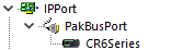
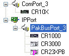
A network is configured by adding each device to the network map in the order that it appears in the actual communication link. For instance, if you are communicating with a CR6 using an IPPort, your network map would consist of an IPPort, a PakBus port, and the CR6:
To add a communication port, press the Add Root button and select a device.
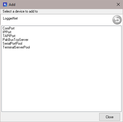
Once a device is added to the network map, the devices shown in the Add box will change, displaying only those devices which are valid connections for the highlighted device in the network map. Continue selecting devices from the Add box until the communication link to the datalogger is represented.
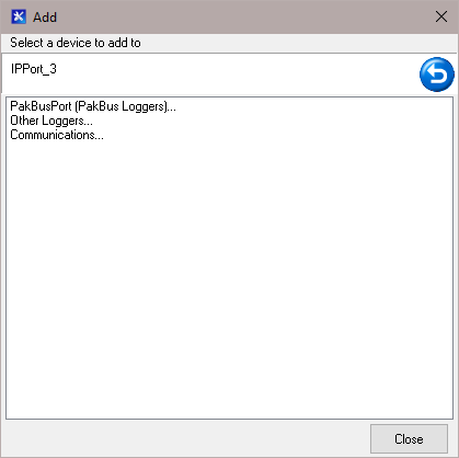
To add a device to an existing device in the network map, highlight the device and press Add. Devices can also be added by highlighting an existing device in the network map and pressing the right mouse button. A list of valid devices that can be added will be displayed.
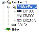
Devices (or device branches) can be moved by clicking on a device (or the top device in a branch) and dragging and dropping it to a new location. For example, in the network map below, the PakBusPort and all of the dataloggers connected to the PakBusPort can be moved from the ComPort to the IPPort by clicking on the PakBusPort and dragging it to the IPPort.
This results in the network map shown below.
A device (and all of its settings) can be copied by selecting the device and pressing Ctrl-C, then pressing Ctrl-V at the position you wish the device to be copied to. Device branches can be copied by selecting the top device in the branch and pressing Shift-Ctrl-C, then pressing Ctrl-V at the position you wish the branch to be copied to. Note that when pasting a root device, you must have a root device selected in your network. The root device being pasted will be inserted in your network below the selected root device. Also note that when using the Undo button (or Ctrl-Z) to undo a copy, each setting for each device will be undone separately. Therefore, it may require pressing the Undo button several times to actually undo the copy. Thus, it may be easier to use the Delete button to remove the device(s).
Ctrl-C (or Shift-Ctrl-C) and Ctrl-V can be used to copy a device (or device branch) to a different LoggerNet network map. Use Ctrl-C (or Shift-Ctrl-C) to copy the device (or device branch) as described above. Open a basic text editor, press Ctrl-V, and then save the file in plain text. Open the text file on the computer where you want to copy the device (or device branch) to, select the entire contents of the file, and then press Ctrl-C. On the LoggerNet network map, select the position you want the device (or device branch) to be copied to and press Ctrl-V.
Applying Changes, Undo, and Redo
The device map is not saved or entered in LoggerNet until you click the Apply button at the bottom of the screen. You can build a complete network and set up the configurations for all of the devices without applying. However, it is a good idea to build the network map in stages and periodically apply changes. If there is a problem with the computer, any changes that have been applied have been saved and will not have to be entered again.
Changing the network map or any of the device settings enables the Undo button. Clicking the Undo button will roll back each change in reverse order to the originally saved network and settings. If you undo a change and really wanted to keep it, you can click the Redo button and restore the change.
Once the changes to the network map and device settings have been applied, they can no longer be rolled back or restored using the Undo or Redo button.
Clicking the Cancel button before changes are applied will undo all of the changes to the network map and settings, and restore the saved configuration.
Renaming Network Devices
The names of all of the devices can be changed as desired. Rename a device by selecting the device and either clicking again with the left mouse button on the selected device or clicking the Rename button. The name of the selected device will change to a text edit box and the new device name can be entered. Valid names consist of letters, numbers and the underscore (_). The device name must be unique in the network and the first character must be a letter.
Device names can reflect a location, layout, or physical location of network devices. Think carefully when naming the devices since these names are used throughout LoggerNet to refer to the devices.
NOTE: Alternately, the Setup Screen (EZ View) can be used to set up the datalogger network.
Toolbar Buttons
|
|
Allows you to choose to view the entire network or a subnet configured using View | Configure Subnets. Available in LoggerNet Admin Only |
|
|
Allows you to choose to view all devices or stations only. Note that when the Stations Only view is enabled, you will not be able to Add, Delete, or Rename devices. |
|
|
Adds a communication port to the device map. |
|
|
Adds a datalogger, modem, or storage device to the device map. |
|
|
Deletes the highlighted device. If the device has other devices attached to it, they will also be deleted. |
|
|
Allows you to change the name of the highlighted device. |
|
|
Reverses any changes that were made since the Apply button was pressed. |
|
|
Reverses the last undo operation. |
|
|
Opens the EZ View of the Setup Screen. |


Menu Items
File
Select Server - Allows you to select the LoggerNet server to which the Setup Screen should connect (available only in LoggerNet Admin/LoggerNet Remote).
Exit - Closes the Setup Screen.
View
EZ (Simplified) – Opens the EZ View of the Setup Screen.
Standard – Opens the Standard View of the Setup Screen.
Configure Subnets – Opens the
Show Hints - When this option is enabled, pop-up hints are displayed when you hover over buttons on the Setup Screen’s toolbar. A check mark appears beside the menu item when enabled.
Backup
Scheduled Backup - Saves a copy of the network to a file on a specified interval. The backup file can then be used to restore the network if necessary. The settings for all the devices in the network will be saved. The *.ini files for each of the applications will be also included in the backup. Ini files store settings such as window size and position, configuration of the data displays, etc.
When this menu item is chosen, the subsequent dialog box allows you to specify the backup base date and time, the backup interval, any additional files to be backed up, whether the backup includes the LoggerNet cache, the name of the backup file, and the number of backup files that will be kept before the oldest is overwritten.
Manual Backup - Saves a copy of the network to a file, which can then be used to restore the network if necessary. The settings for all the devices in the network will be saved. The *.ini files for each of the applications will be also included in the backup. Ini files store settings such as window size and position, configuration of the data displays, etc.
When this menu item is chosen, the subsequent dialog box offers an additional option:
Include Cache Table Files in the Backup - If this check box is selected, the LoggerNet Server Data Cache will be included in the backup.
After selecting Next, you will be provided with another dialog box that can be used to add files to the backup file. By default, user files, such as the *.dat files that are created when you collect data from a datalogger, the program files created by Edlog or CRBasic, and the files created when running Split, are not included in the backup. They can be added to the backup from this window if desired. When Next is selected again, you are prompted for a file name for the backup. After supplying a file name, you can choose to execute the backup or save the backup configuration file for later use.
A network backup file can also be created from a task, by LNBackup.exe. See Example #2 under Task Master for additional information on this utility.
Restore Network - Restores the network map from a backup file. Select the name of the backup file to restore from the first dialog box, and press Next. Select whether or not network communications will be enabled, when the network is restored. Press the Restore button. Note that this backup will replace the existing network (it does not add to the existing network), and any existing files, including data files, program files, or Split files if they were included in the original backup.
Tools
LoggerNet Server Settings
LoggerNet Settings: Used to select what time option will be used for the LoggerNet server. Options are to use GMT, or use local server time with or without adjustment for daylight saving time. Also used to set the maximum size for data files and to enable/disable communications for the entire datalogger network.
PakBus Settings: LoggerNet can be configured so that all PakBus ports in the network map are part of one PakBus network, or so that each PakBus port in the network map will be an independent PakBus network. This menu item is used to set up this aspect of LoggerNet and assign either a global PakBus port ID for LoggerNet or IDs for each PakBus port. Valid PakBus IDs are 1 through 4094, though typically numbers greater than 3999 are used for PakBus ports. This is because, when a neighbor filter is set up, a PakBus datalogger will answer a Hello message from any device with an ID greater than 3999, but will ignore devices with IDs less than 4000 that are not in their neighbor list.
LoggerNet Defaults: This option is used to set default values for the Schedule, Data Files, File Retrieval, and Clock tabs that will be used when new devices are added to the network. The dialog box can also be used to copy the specified defaults to existing stations.
Copy Device Settings- Opens
TroubleShooter - Opens the TroubleShooter application. This application is used to help discover the cause of communication problems in a datalogger network.
Help
Setup Screen Help – Opens LoggerNet’s online help system to Setup Screen specific help.
About Setup Screen – Provides copyright and version number information for the Setup Screen.
Network Analysis
In addition to the TroubleShooter, the Setup Screen has two problem boxes that display potential problems with the network.
The first is a device-specific problem box that is shown at the bottom of the Setup Screen. If no problems are detected for a device, the text in the box will read "No problems found with settings for the selected device." However, if some potential device conflict or other problem is found, it will be indicated here. Some instances for which a message will be displayed are: if communication is disabled for a device, if a device has the same PakBus ID as another device in the network, or if a COM port is placed in the device map twice. Clicking on a potential problem will bring up a menu that allows you to fix the potential problem or get additional help.
The second problem box provides a list of problems found with all devices in the network map. To display this information, press the Check button. Any potential problems that exist with the network will be listed, including the use of conflicting communication ports, duplicate device IDs, and disabled scheduled data collection. Clicking on a potential problem in the list will bring up a menu that allows you to fix the potential problem or get additional help.