Resistance
The Resistance instruction is used to measure resistance of a basic or full-bridge circuit.
Syntax
Resistance ( Dest, Reps, Range, DiffChan, IexChan, MeasPEx, EXuA, RevEx, RevDiff, SettlingTime, fN1, Mult, Offset, MeasCurrent [optional] )
Following are wiring diagrams and example code for measuring one or more sensors.
Example #1: Measure three sensors with one excitation channel
This configuration allows a precision 4-wire measurement to be made of three sensors using a single U channel for excitation (U7). The sensors need to be connected in series with each sensor using independent U and signal ground terminals.
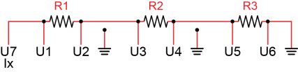
Resistance (Dest(),3,mV5000,U1,U7,3,2500,True,True,0,60,1.0,0)
Example #2 Measure PT-100 with Current excitation
'This program example demonstrates the measurement of 100-ohm PRT (PT-100)
'with current excitation.
Const RS0 = 100 'Resistance of PT100 at 0 °C
Public X 'Raw output from the bridge
Public RS 'Calculated PT100 resistance
Public RS_RS0 'Calculated ratio RS/RS0
Public DegC 'Calculated temperature
BeginProg
Scan(1,Sec,0,0)
'Measure X:
Resistance(X,1,mV200,U3,U1,1,250,True,True,0,60,1,0)
'Calculate RS and RS_RS0:
RS = X
RS_RS0 = RS/RS0
'Calculate temperature from RS_RS0:
'PRTCalc(Dest,Reps,Source,PRTType,Mult,Offset)
PRTCalc(DegC,1,RS_RS0,1,1.0,0)
NextScan
EndProg
Example #3: Measure one sensor on a differential channel
To reduce the number of channels used, it is possible to use a U terminal for both current excitation and sensor measurement, but this configuration decreases the accuracy of the measurement since the datalogger does not compensate for the resistance of the wires between the logger and the sensor. For relatively high resistance sensors such as thermistors, the error resulting from this configuration is often insignificant. However, using the same U terminal for both current excitation and measurement will result in significant error for low-resistance sensors, such as the PT-100 or single-element strain gauges.
NOTE: For low-resistance sensors, consider using Resistance3W(), which removes voltage offset errors due to the datalogger measurement circuitry, including operational input voltage errors.
NOTE: The sensor must be tied to ground in order to complete the current excitation loop.
Public Dest 'Destination variable
DataTable(TEST, 1, 1000)
DataInterval(0,10,Sec, 10)
Average(1,Dest, FP2, 0)
EndTable
'Main Program
BeginProg
Scan( 1,Sec, 1, 0 )
'measure Resistance on Diff Chnl 1
Resistance (Dest,1,mv5000,U1,U1,1,2500,True,True,0,15000,1.0,0)
CallTable TEST
NextScan
EndProg
Remarks
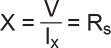
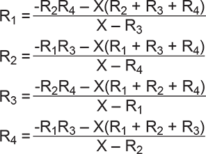
The resistance is determined by applying a known excitation current to a circuit and dividing the resultant voltage by the excitation current. The maximum excitation current is 2500 μA. If multiple sensors are measured during current excitation, the sensors should be connected in series rather than in parallel. The sum of the voltages that develops across each resistor when the excitation current is applied cannot exceed the specified compliance voltage for each excitation channel (+/- 5V). The MeasPEx and ExuA arguments are used to specify the number of sensors to excite with a given excitation channel. The output of the measurement is in Ohms. Example calculations are provided below.
Wiring diagrams for one or more sensors are shown in the example program.
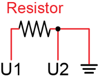
Resistance, Basic Circuit
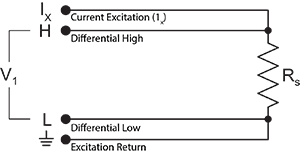
Resistance, Full-Bridge Circuit
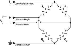
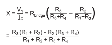
Relational Formulas:
NOTE: Channel assignments for this instruction must fall within the guidelines for universal terminal pairs.
Parameters
Dest (Destination)
The Variable in which to store the results of the instruction. Right-click the parameter to display a list of defined variables.
If this instruction has a Repetitions parameter and it is greater than 1, the results are stored in an array with the variable name. The array must be dimensioned large enough to hold all of the values returned from all of the Reps.
Type: Variable or Array
Reps (Repetitions)
The number of repetitions for the measurement or instruction.
Type: Constant integer (or expression that evaluates as a constant).
Range
The expected voltage range of the input from the sensor. An alphanumeric code is entered:
| Code | Description |
|---|---|
| mV5000 | ±5000 mV |
| mV1000 | ±1000 mV |
| mV200 | ±200 mV |
Type: Constant
DiffChan (Differential Channel)
Specifies the
If the DiffChan number is entered as a negative value, all Reps are
performed on the same channel (burst measurement). The CR6 burst measurement sampling
| Code | Description |
|---|---|
| U1 | Universal Terminals 1 and 2 (U1 = high/U2 = low) |
| U3 | Universal Terminals 3 and 4 (U3 = high/U4 = low) |
| U5 | Universal Terminals 5 and 6 (U5 = high/U6 = low) |
| U7 | Universal Terminals 7 and 8 (U7 = high/U8 = low) |
| U9 | Universal Terminals 9 and 10 (U9 = high/U10 = low) |
| U11 | Universal Terminals 11 and 12 (U11 = high/U12 = low) |
Type: Constant
IxChan
The number of the current excitation channel to excite the first measurement. When a series of sensors are measured with the same instruction, the MeasPEx parameter is used to determine how many sensors to excite with one excitation channel before advancing to the next. Right-click the parameter to display a drop-down list box.
| Code | Description |
|---|---|
| U1 | Universal terminal 1 |
| U2 | Universal terminal 2 |
| U3 | Universal terminal 3 |
| U4 | Universal terminal 4 |
| U5 | Universal terminal 5 |
| U6 | Universal terminal 6 |
| U7 | Universal terminal 7 |
| U8 | Universal terminal 8 |
| U9 | Universal terminal 9 |
| U10 | Universal terminal 10 |
| U11 | Universal terminal 11 |
| U12 |
Universal terminal 12 |
Type: Constant
MeasPEx (Excitation Channels)
The MeasPEx argument specifies the number of sensors to excite with the same excitation channel before automatically advancing to the next excitation channel. To excite all sensors with the same excitation channel, the value of MeasPEx should be set equal to the Reps parameter.
If multiple sensors are measured during current excitation, the sensors should be connected in series, rather than in parallel. For example, instead of connecting the low side of the resistor to ground, the low side connects to the high side of the next resistor being measured. The last resistor in the chain will tie to ground. With the sensors connected in series, you need to consider the voltage that develops across each resistor when the excitation current is applied (V = IR). The sum of these voltages cannot exceed the specified compliance voltage for each excitation channel (+/- 5V). For example, if you’re exciting a string of 350-ohm resistors with the full 2.5 mA of current excitation, the voltage across each resistor is 0.0025 * 350 = 0.875 V per resistor. Then, 5 V compliance voltage/ 0.875 V per resistor = 5.714 resistors. So, you could measure up to five 350-ohm resistors per excitation channel. Hence, to measure eight of these sensors, 8 would be entered for the Reps argument and 5 for the MeasPEx argument. The first 5 sensors would all be connected to the first excitation channel, and the next 3 to the second excitation channel.
ExuA (Current Excitation in μA)
The ExuA argument is the current excitation, in μAmps, to apply to the sensor. The allowable range is ±2500 μA. Reducing the excitation current may allow additional sensors to be excited with one excitation channel. For example, in the example above for MeasPEx, if we decrease the excitation current to 2 mA , (V=IR), 0.002 * 350 = 0.7 V per resistor. Then divide the maximum compliance voltage for an excitation channel (5 V) by the volts per sensor: 5 V/0.7 V per resistor = 7.14 resistors. So, by decreasing the excitation current to 2 mA instead of 2.5 mA, you could measure up to seven 350-ohm resistors per excitation channel. Note that because output for this instruction is ratometric, output is scaled to the excitation current.
RevEx (Reverse Excitation)
Type: Constant
Reverse Differential (RevDiff)
A constant value is entered to determine whether the inputs are reversed and a second measurement made. This removes any voltage offset errors due to the datalogger measurement circuitry, including
| Logic | Description |
|---|---|
| False or 0 | Signal is measured with the high side referenced to the low. Do not make second measurement. |
| True or 1 | Reverse input and make second measurement. |
Type: Constant or Variable
Settling Time
The settling time is the duration (in microseconds) to allow for signal settling after setting up a measurement (switching to the channel, setting the excitation) and before making the measurement.
Additional settling time may be necessary to allow the signal to settle with high resistance or long lead lengths (higher capacitance). The time it will take to make the measurement will include the measurement itself, the SettlingTime, fN1, and whether or not parameters are set to remove voltage offset errors. Using either RevDiff or RevEx causes two SettlingTimes to occur per channel; four SettlingTimes will occur when using both RevDiff and RevEx.
Type: Constant (or expression that evaluates as a constant)
fN1
Determines the lowest frequency that will be eliminated or notched out by the sinc filter. This filter notches out frequencies at integer multiples of fN1 by averaging for a time equal to 1/fN1;
thus, lower fN1 frequencies result in longer measurement times.
| Option | Description |
|---|---|
| 15000 | Performs a 0.0667 millisecond integration (for fast measurements) |
| 60 (or _60Hz) | Performs a 16.67 millisecond integration (filters 60 Hz noise) |
| 50 (or _50Hz) | Performs a 20 millisecond integration (filters 50 Hz noise) |
Type: Constant
Mult, Offset (Multiplier and Offset)
Factors by which to scale the raw results of the measurement. Typically used to convert the raw measurement to engineering units or to units other than which is output. For example, the TCDiff instruction measures a thermocouple and outputs temperature in degrees C. A multiplier of 1.8 and an offset of 32 will convert the temperature to degrees F.
For temperature measurements, a multiplier (mult) of 1 and an offset of 0, would output in degrees Celsius. For analog measurements, a multiplier (mult) of 1 and an offset of 0, would output the measured voltage in millivolts divided by the excitation voltage in volts.
If Repetitions of greater than 1 are used for this instruction, Repetitions can also be used for the Multiplier and Offset. See Multipliers, Offsets, and Disable Variables with Repetitions for more information.
Type: Constant, Variable, Array, or Expression
Optional Parameter
MeasCurrent
An optional parameter
Measurement Time
The minimum time it will take to make the measurement will include the settling time, 850 microseconds to flush old data from the ![]() ADC Analog to digital conversion. The process that translates analog voltage levels to digital values., fN1, and whether or not the instruction removes voltage offset errors.
ADC Analog to digital conversion. The process that translates analog voltage levels to digital values., fN1, and whether or not the instruction removes voltage offset errors.
In addition, 6 milliseconds is required for the datalogger to prepare for making measurements (referred to as the sinc time). If the program is running in pipeline mode, the sinc is done for the first measurement only. If the program is running in sequential mode, the sinc takes place with each measurement instruction (but not with subsequent reps of an instruction).
If the total scan interval minus the scan measurement time is less than 50 microseconds, analog power is left on and the ![]() ADC Analog to digital conversion. The process that translates analog voltage levels to digital values. requires only about 1 microsecond to "wake up".
ADC Analog to digital conversion. The process that translates analog voltage levels to digital values. requires only about 1 microsecond to "wake up".
NOTE: This instruction must NOT be placed inside a conditional statement when running in pipeline mode.