Resistance3W ( 3-Wire Resistance Measurement)
The Resistance3W instruction is used to make a 3-wire resistance measurement.
Syntax
Resistance3W ( Dest, Reps, Range, UChan, IXuA, RevEx, SettlingTime, fN1, Mult, Offset, )
Public ResValue
DataTable(Test,1,-1)
DataInterval(0,15,Sec,10)
Sample(1,ResValue,FP2)
EndTable
BeginProg
Scan(1,Sec,1,0)
Resistance3W (ResValue,1,mV5000,U1,2500,True ,0,60,1.0,0)
CallTable Test
NextScan
EndProg
Remarks
This instruction makes three measurements. First, to compute the circuit current, the specified excitation current is applied and the voltage across the internal precision resistor is measured differentially (Vi). The inputs are then reversed and a second measurement is made. This removes any voltage offset errors due to the datalogger measurement circuitry, including operational input voltage errors. Next, the specified channel is measured as a single ended measurement (V1). Finally, the next higher channel is measured as a single ended measurement (V2).
The instruction returns Rs = (2*V2-V1) Ri / Vi
where Ri is the precision internal resistor value that is saved as part of the factory calibration procedure and Rs is the sensor resistance.
If reverse excitation (RevEx) is specified, it is performed on all three measurements.
The following image shows the measurements. Rw is the resistance of the lead wires. These are assumed to be matched.
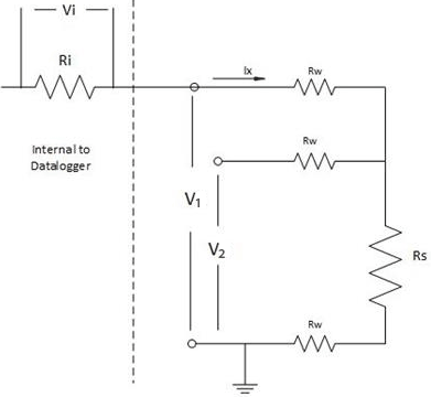
Rs = (2*V2-V1) Ri / Vi
Parameters
Dest (Destination)
The Variable in which to store the results of the instruction. Right-click the parameter to display a list of defined variables.
If this instruction has a Repetitions parameter and it is greater than 1, the results are stored in an array with the variable name. The array must be dimensioned large enough to hold all of the values returned from all of the Reps.
Type: Variable or Array
Reps (Repetitions)
The number of repetitions for the measurement or instruction.
Type: Constant integer (or expression that evaluates as a constant).
For the Resistance3W measurement, measurements are made on consecutive channels. If the Reps parameter is greater than 1, the Dest parameter must be a variable array.
Range
The expected voltage range of the input from the sensor. An alphanumeric code is entered:
| Code | Description |
|---|---|
| mV5000 | ±5000 mV |
| mV1000 | ±1000 mV |
| mV200 | ±200 mV |
Type: Constant
UChan (Universal Channel)
Specifies the number of the universal terminal pair on which to make the first measurement. If the Reps parameter is greater than 1, additional measurements will be made on sequential channels.
If the UChan number is entered as a negative value, all Reps are performed on the same channel (burst measurement). The CR6 burst measurement sampling frequency is determined by the fN1 (first notch frequency) parameter, which can go up to a maximum of 93750 Hz (minimum sample interval of 10.667 uS). The SettlingTime parameter is used to delay once prior to beginning the burst. The total time prior to beginning the burst is the SettlingTime plus the ADC flush time (which is 810uS). The sample interval resolution is 1/93750Hz. The specified notch frequency will use the nearest multiple of (1/93750Hz) to get as close to the specified frequency as possible.
| Code | Description |
|---|---|
| U1 | Universal Terminals 1 and 2 |
| U3 | Universal Terminals 3 and 4 |
| U5 | Universal Terminals 5 and 6 |
| U7 | Universal Terminals 7 and 8 |
| U9 | Universal Terminals 9 and 10 |
| U11 | Universal Terminals 11 and 12 |
Type: Constant
IxUA (Current Excitation in µAmps)
The current excitation, in microAmps, to apply to the excitation channel. The allowable range is ±2500 µA. For ExciteI() only, with DiffEx set to 1, the allowable range is ±12500 µA.
Type: Constant
RevEx (Reverse Excitation)
Type: Constant
Settling Time
The settling time is the duration (in microseconds) to allow for signal settling after setting up a measurement (switching to the channel, setting the excitation) and before making the measurement.
Additional settling time may be necessary to allow the signal to settle with high resistance or long lead lengths (higher capacitance). The time it will take to make the measurement will include the measurement itself, the SettlingTime, fN1, and whether or not parameters are set to remove voltage offset errors. Using either RevDiff or RevEx causes two SettlingTimes to occur per channel; four SettlingTimes will occur when using both RevDiff and RevEx.
Type: Constant (or expression that evaluates as a constant)
fN1
Determines the lowest frequency that will be eliminated or notched out by the sinc filter. This filter notches out frequencies at integer multiples of fN1 by averaging for a time equal to 1/fN1;
thus, lower fN1 frequencies result in longer measurement times.
| Option | Description |
|---|---|
| 15000 | Performs a 0.0667 millisecond integration (for fast measurements) |
| 60 (or _60Hz) | Performs a 16.67 millisecond integration (filters 60 Hz noise) |
| 50 (or _50Hz) | Performs a 20 millisecond integration (filters 50 Hz noise) |
Type: Constant
Mult, Offset (Multiplier and Offset)
Factors by which to scale the raw results of the measurement. Typically used to convert the raw measurement to engineering units or to units other than which is output. For example, the TCDiff instruction measures a thermocouple and outputs temperature in degrees C. A multiplier of 1.8 and an offset of 32 will convert the temperature to degrees F.
For temperature measurements, a multiplier (mult) of 1 and an offset of 0, would output in degrees Celsius. For analog measurements, a multiplier (mult) of 1 and an offset of 0, would output the measured voltage in millivolts divided by the excitation voltage in volts.
If Repetitions of greater than 1 are used for this instruction, Repetitions can also be used for the Multiplier and Offset. See Multipliers, Offsets, and Disable Variables with Repetitions for more information.
Type: Constant, Variable, Array, or Expression
Measurement Time
The minimum time it will take to make the measurement will include the settling time, 850 microseconds to flush old data from the ![]() ADC Analog to digital conversion. The process that translates analog voltage levels to digital values., fN1, and whether or not the instruction removes voltage offset errors.
ADC Analog to digital conversion. The process that translates analog voltage levels to digital values., fN1, and whether or not the instruction removes voltage offset errors.
In addition, 6 milliseconds is required for the datalogger to prepare for making measurements (referred to as the sinc time). If the program is running in pipeline mode, the sinc is done for the first measurement only. If the program is running in sequential mode, the sinc takes place with each measurement instruction (but not with subsequent reps of an instruction).
If the total scan interval minus the scan measurement time is less than 50 microseconds, analog power is left on and the ![]() ADC Analog to digital conversion. The process that translates analog voltage levels to digital values. requires only about 1 microsecond to "wake up".
ADC Analog to digital conversion. The process that translates analog voltage levels to digital values. requires only about 1 microsecond to "wake up".
NOTE: This instruction must NOT be placed inside a conditional statement when running in pipeline mode.