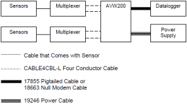
Multiplexers controlled by
Direct RS-232 connection
For this configuration, vibrating-wire sensors are attached to multiplexers, which are controlled by the . The is connected directly to the data logger.
Do the following:
-
If a multiplexer other than the default is being used, go to the Deployment/Measurement tab in Device Configuration Utility and select the correct multiplexer (Connecting to Device Configuration Utility and Communications). The default multiplexer for the is the AM16/32A.
-
Attach the multiplexers to the as shown in Example AM16/32-series to AVW200 hookup (multiplexers controlled by AVW200).
-
Connect the sensors to the multiplexers. Refer to the AM16/32B relay multiplexer manual: https://s.campbellsci.com/documents/us/manuals/am16-32b.pdf
 .
. -
Use the serial cable to attach the to control port pairs on the data logger, or use the null modem cable to attach the to the data logger RS-232 port.
-
Connect one end of the power cable to the 12V and G terminals on the and the other end to the 12V and G terminals on the data logger or external power supply. Refer to Power and ground and Data logger wiring for a direct connection for more information.
-
Create a CRBasic program that includes the
AVW200()instruction for each multiplexer to be controlled by the.For example, the following
AVW200()instructions can be used to control two multiplexers:AVW200(Data1(),ComC1,200,200,mux1(1,1),1,1,16,450,3000,2,_60HZ,1,0)AVW200(Data2(),ComC1,200,200,mux2(1,1),2,1,16,450,3000,2,_60HZ,1,0)
where:
connects to data logger control ports C1/C2 via serial cable (option Com1)
Each multiplexer has 16 sensors connected to it
Begin frequency = 450
End frequency = 3000
Excitation voltage = 12 VDC peak to peak (option 2)
Refer to Programming with the AVW200() instruction for details about the AVW200() instruction and its parameters and to AVW200() instruction controlling two multiplexers, AVW200() instruction running in pipeline mode, and AVW200 controlling two multiplexers in sequential mode for complete example programs that control two multiplexers.
Wireless connection
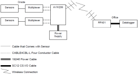
For this configuration, vibrating-wire sensors are attached to multiplexers, which are controlled by an AVW206. The AVW206 interface transmits the data to an RF401A spread spectrum radio that is connected to the data logger.
At the AVW206 site, do the following:
-
Use Device Configuration Utility to configure the AVW206 for RF communications (Connecting to Device Configuration Utility and Communications).
-
If a multiplexer other than the default is used, go to the Deployment/Measurement tab in Device Configuration Utility and select the applicable multiplexer (Connecting to Device Configuration Utility and Communications). The default multiplexer for the AVW206 is the AM16/32A.
-
Attach the multiplexers to the AVW206 as shown in Example AM16/32-series to AVW200 hookup (multiplexers controlled by AVW200).
-
Connect the sensors to the multiplexers. Refer to the AM16/32B relay multiplexer manual: https://s.campbellsci.com/documents/us/manuals/am16-32b.pdf
 .
. -
Attach a Yagi or omnidirectional antenna to the antenna connector on the side of the AVW206. Refer to Antennas, antenna cables, and surge protectors for the AVW206, AVW211, and AVW216 for a description of antenna options.
-
Use the power cable to connect the 12V and G terminals on the AVW206 to the 12V and G terminals on the PS100 or another power supply.
At the data logger/RF401A site, do the following:
-
Configure the RF401A radio so its parameters match the AVW206.
NOTE:The protocol setting for the RF401A must be PB Aware or PB Node.
-
Attach a Yagi or omnidirectional antenna to the antenna connector on the RF401A.
-
Use an SC12 serial cable to attach the data logger CS I/O port to the RF401A CS I/O port. The data logger CS I/O port powers the RF401A. Refer to the spread spectrum data radio/modem manual for more information: https://s.campbellsci.com/documents/us/manuals/rf401a-series.pdf
 .
. -
Create a CRBasic program that includes the
AVW200()instruction for each multiplexer controlled by the .For example, the following
AVW200()instructions can be used to control the multiplexers:AVW200(Data1(),ComSDC7,200,200,mux1(1,1),1,1,16,450,3000,2,_60HZ,1,0)AVW200(Data2(),ComSDC7,200,200,mux2(1,1),2,1,16,450,3000,2,_60HZ,1,0)
where:
RF401A = configured for SDC7
Each multiplexer has 16 sensors connected to it
Begin frequency = 450
End frequency = 3000
Excitation voltage = 12 VDC peak to peak (option 2)
Refer to Programming with the AVW200() instruction for details about the AVW200() instruction and its parameters and to Wireless/sensors with different frequencies for a complete example program that controls two multiplexers.

