QuickStart
Short Cut is an easy way to program the data logger to make measurements through an AM16/32B multiplexer. Short Cut is included in installations of LoggerNet, RTDAQ, and PC400. It is also available as a download on www.campbellsci.com![]() . Short Cut supports the CR6, CR3000, CR1000X, CR800-series, and CR1000 data loggers when creating a program to take measurements through an AM16/32B. Short Cut does not include support for programming the CR300-series to use the AM16/32B. To use the AM16/32B with the CR300 series, the program must be created in the CRBasic Editor. See Single-ended voltage measurement and Differential voltage measurement for CR300-series programming examples.
. Short Cut supports the CR6, CR3000, CR1000X, CR800-series, and CR1000 data loggers when creating a program to take measurements through an AM16/32B. Short Cut does not include support for programming the CR300-series to use the AM16/32B. To use the AM16/32B with the CR300 series, the program must be created in the CRBasic Editor. See Single-ended voltage measurement and Differential voltage measurement for CR300-series programming examples.
This section will demonstrate programming a data logger to measure 6 Campbell Scientific 107 temperature sensors using a multiplexer. With minor changes, these steps can also be applied to other measurements and data loggers.
|
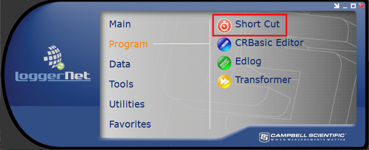
Open Short Cut. From the LoggerNet toolbar, click Program > Short Cut. In PC400, click on the Short Cut icon. |
|
|
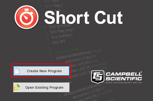
Select Create New Program. |
|
|
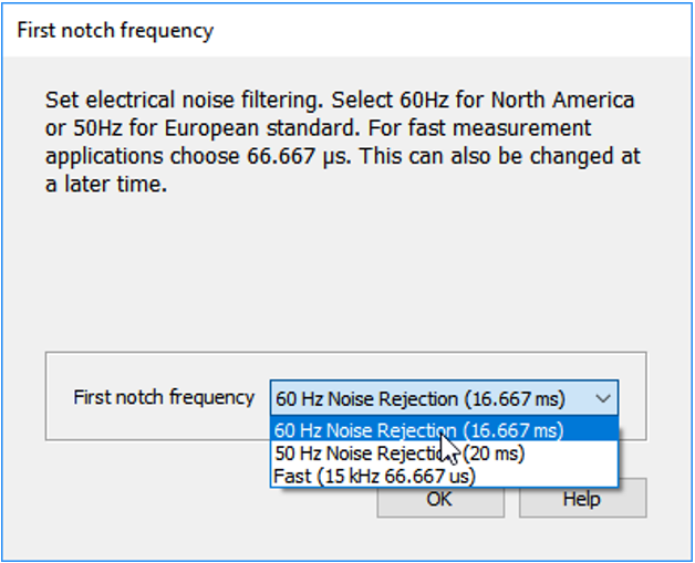
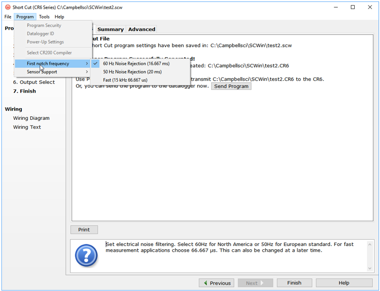
NOTE: The first time Short Cut is run, a prompt will appear asking for a choice of first notch frequency. Select 60 Hz Noise Rejection for the United States and areas using 60 Hz AC voltage. Select 50 Hz Noise Rejection for most of Europe and areas that operate at 50 Hz. |
|
|
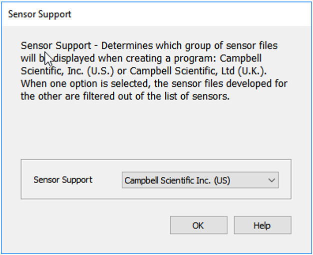
A second prompt lists sensor support options. Campbell Scientific, Inc. (US) is the best option outside Europe. |
|
|
To change the first notch frequency or sensor support option for future programs, use the Program menu. |
|
|
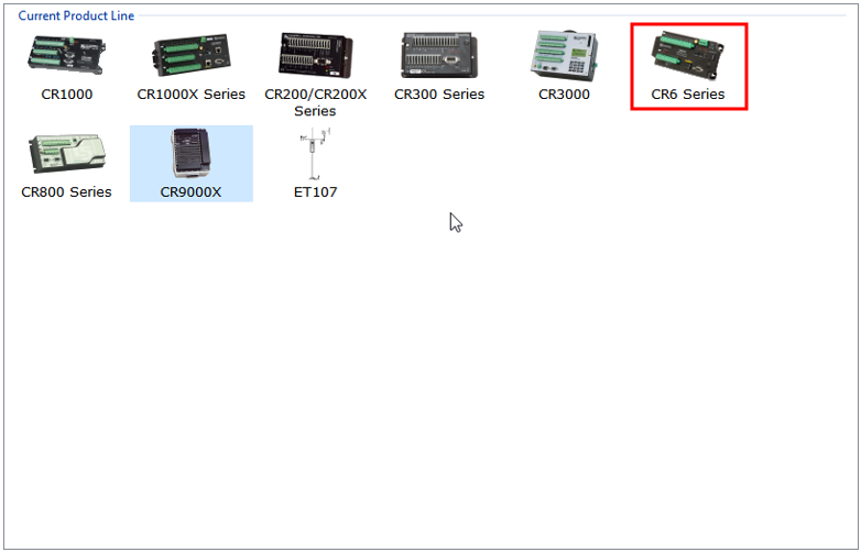
Select the data logger model in the Datalogger Model drop-down list. This tutorial uses the CR6-series data logger. |
|
|
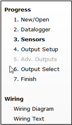
The Progress Bar is used to track the progress of the program being created. It is also used to jump directly to any step in the programming process. |
|
|
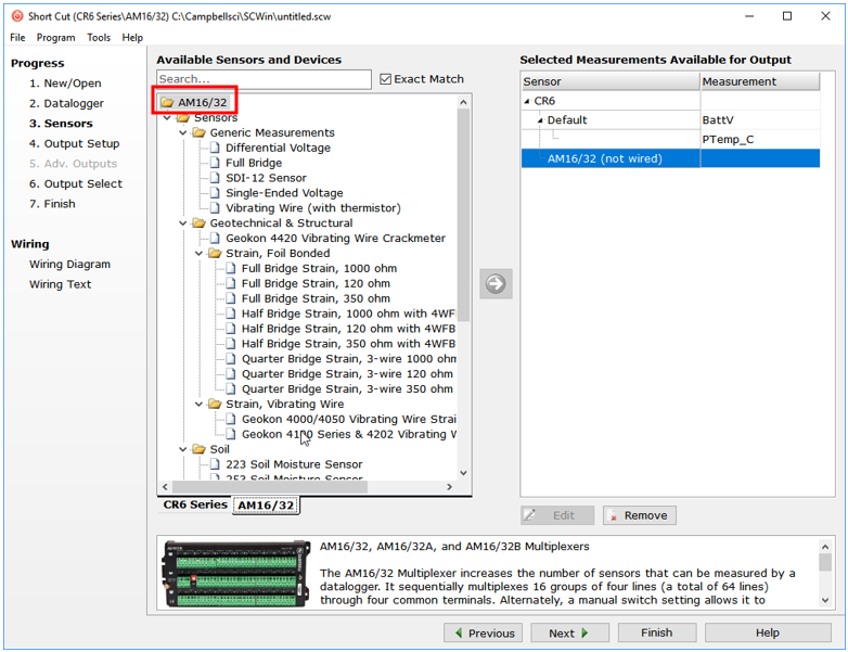
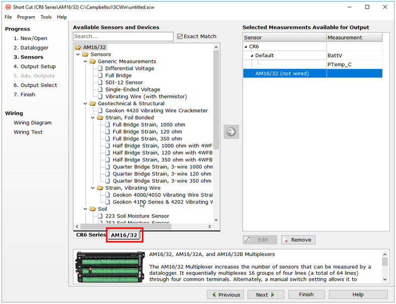
The next window displays Available Sensors and Devices. Expand a folder by clicking on the symbol. Expand the Devices folder, then double-click on the AM16/32 to add it to the Selected panel. |
|
|
When the AM16/32 multiplexer is added as a device, a new AM16/32 tab will appear at the bottom of the Available Sensors and Devices pane. With the AM16/32 tab selected, select the Sensors > Temperature subfolder. Doubleclick on 107 Temperature Probe (4-wire). |
|
|
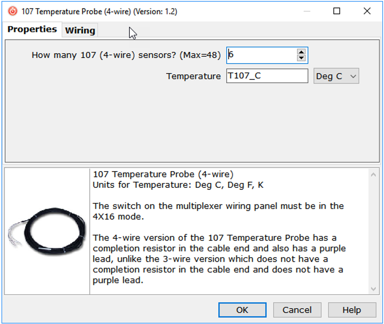
In the resulting window, enter the number of 107 temperature probes to measure on this AM16/32B multiplexer. For this tutorial, enter 6 as the number of 107 (4-wire) sensors to add. Click OK in the dialog window to accept the default name of T107_C and the default units of Deg C. |
|
|
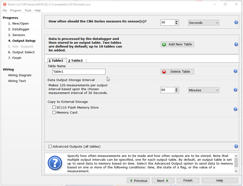
In the Scan Interval box, enter how frequently the data logger should make measurements. When measuring with an AM16/32B multiplexer, an interval of 30 seconds or longer is recommended. Enter 30 and select Seconds. Click Next. |
|
|
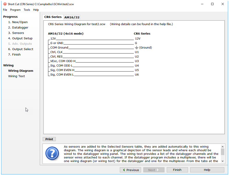
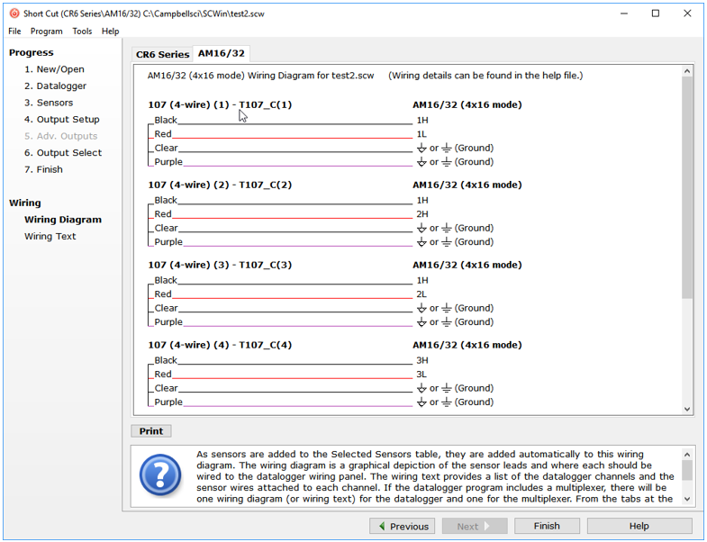
After adding the measurements, click Wiring Diagram to see how the sensors are wired to the AM16/32B and how the AM16/32B is wired to the data logger. The data logger tab (CR6 Series in this example) shows the connection between the AM16/32B and the data logger, and the AM16/32 tab shows the sensor connection to the AM16/32B. |
|
|
With power disconnected, wire the sensors and devices as shown in the wiring diagrams. Insert the wires, taking care to tighten the terminals on the conductors themselves, not the insulation. |
|
|
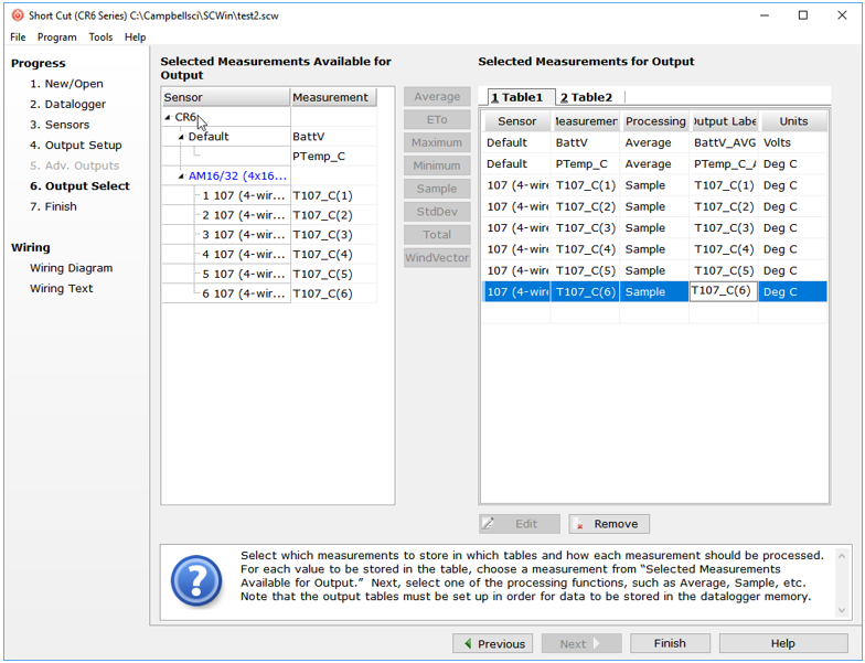
Click on Sensors in the Progress list to return to the sensor-selection screen. Select any other sensors being installed in the Sensors section. Add sensors to the data logger by selecting the data logger tab (CR6 in this example). Add sensors to the multiplexer by selecting the AM16/32 tab. Finish the remaining Short Cut steps to complete the program. The remaining steps are outlined in Short Cut Help, which is accessed by clicking on Help > Short Cut Help > Contents > Programming Steps. |
|
|
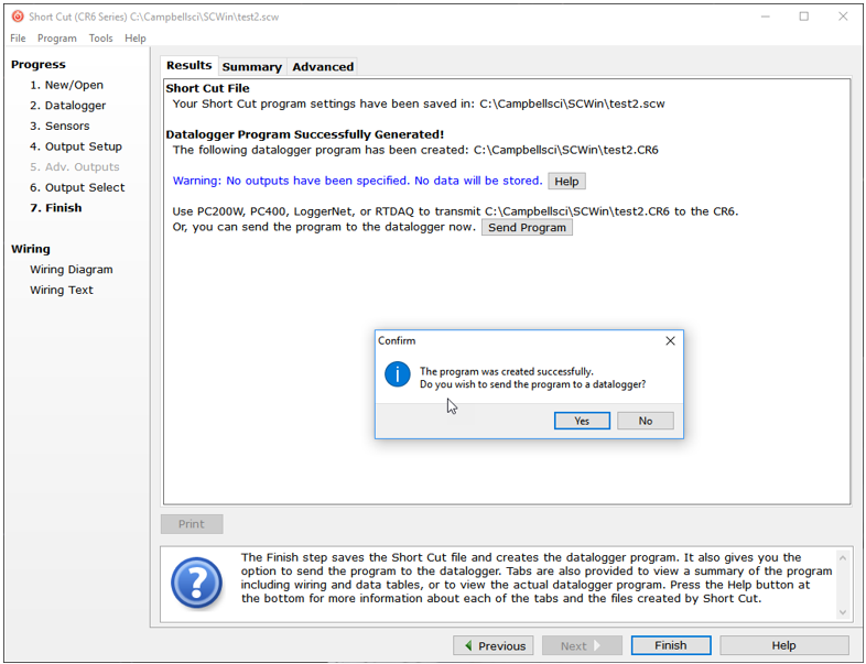
If LoggerNet, RTDAQ, or PC400 is running on the computer and the computer-to-data-logger connection is active, click Finish in Short Cut, and a prompt will appear to send the program just created to the data logger. |
|
|
After powering on and sending the program to the data logger, check the output of sensors in the data logger support software data display to make sure the measurements are within the expected range. |
|