Current-loop measurements
NOTE:
This information applies to CR6 data loggers with serial numbers 7502 and greater. These data loggers have two blue stripes on the label.
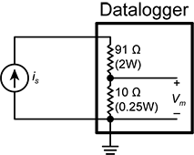
RG terminals can be configured to make analog current measurements using the CurrentSE() instruction. When configured to measure current, terminals each have an internal resistance of 101 Ω in the current measurement loop. The return path of the sensor must be connected directly to the RG terminal. The following image shows a simplified schematic of a current measurement.
Example current-loop measurement connections
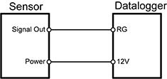
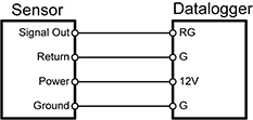
The following table shows example schematics for connecting typical current sensors and devices. See also Current-loop measurement specifications.
| Sensor type |
Connection example |
| 2-wire transmitter using data logger power |
|
| 2-wire transmitter using external power |
|
| 3-wire transmitter using data logger power |
|
| 3-wire transmitter using external power |
|
| 4-wire transmitter using data logger power |
|
| 4-wire transmitter using external power |
|


