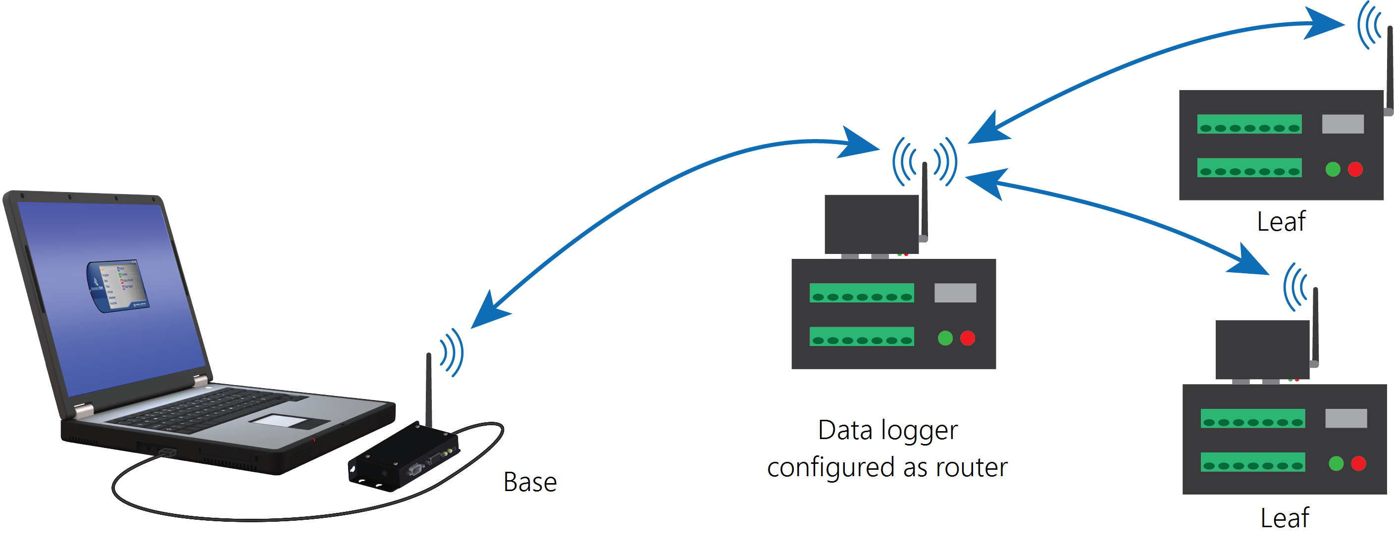
RF407-series radio communications with multiple data loggers through a data logger router
This type of network configuration is useful for communicating around an obstacle, such as a hill or building, or to reach longer distances.
(Click image to expand/collapse display)
Most Campbell Scientific devices come from the factory with a default PakBus address of 1. For this reason, it is best not to assign PakBus address 1 to any device in the network. Then, if a new device with default settings is added to the system, it will not create a conflict.
Configure the RF407-series base radio
Configure the base radio. This is the RF407-series radio that is connected to the computer (see previous image for reference).
-
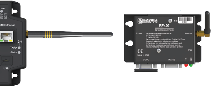
Ensure that an antenna is connected to the RF407-series radio.
-
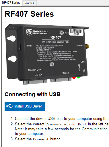
If connecting via USB for the first time, you must first install USB drivers using Device Configuration Utility (select your radio, then on the main page, click Install USB Driver).

(Click image to expand/collapse display) -
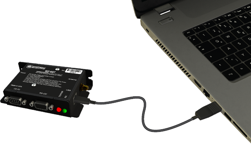
Connect the USBport on your RF407-series radio to your computer.

(Click image to expand/collapse display) -
Using Device Configuration Utility, select the Communication Port used for your radio and connect to the RF407-series radio.
-
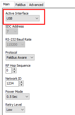
On the Main tab, set the Active Interface to USB or RS-232 (depending on how your computer will be connected to the RF407-series radio).

(Click image to expand/collapse display) -
Apply to save your changes.
-
The TX/PWR and RX LEDs flash once, after which the TX/PWR LED returns to blinking at the Power Mode interval (0.5 sec, by default).
Configure the data logger acting as a router
-
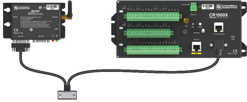
Ensure the antenna is connected.
(Click image to expand/collapse display) -
For data loggers with an external radio, connect the radio and data logger CS I/O ports using an SC12 cable.
(Click image to expand/collapse display) -
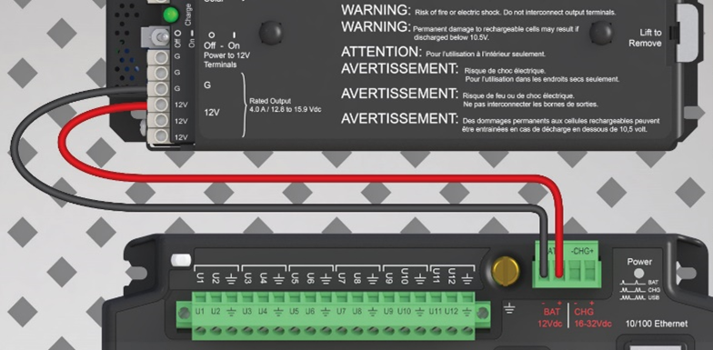
Supply 12 VDC power to the data logger.
-
connect 12 VDC at the green BAT terminals
-
or connect 16 to 32 VDC at the CHG terminals

(Click image to expand/collapse display) -
-
If connecting via USB for the first time, you must first install USB drivers using Device Configuration Utility (select your radio, then on the main page, click Install USB Driver).
(Click image to expand/collapse display) -
Using Device Configuration Utility, connect to the data logger that will serve as a router.
-
On the Deployment > Datalogger tab, assign a unique PakBus address
-
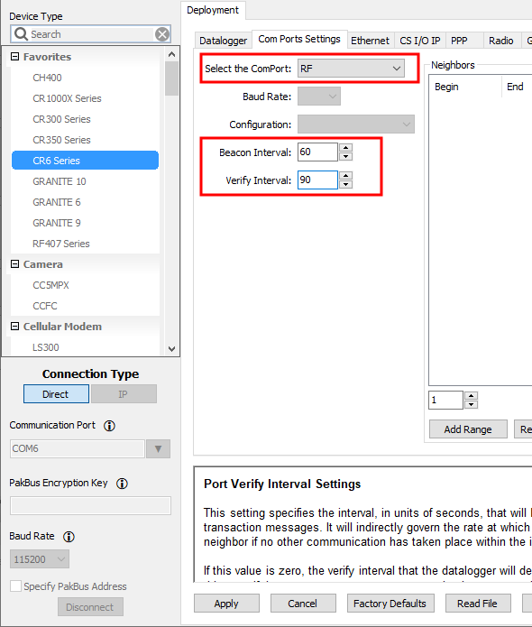
On the Deployment tab, click the Com Ports Settings sub-tab.
-
From the Select the ComPort list, select RF.
-
Set the Beacon Interval to 60 seconds (or the amount of time you are willing to wait for the
 leaf A PakBus node at the end of a branch. When in this mode, the data logger is not able to forward packets from one of its communications ports to another. It will not maintain a list of neighbors, but it still communicates with other PakBus data loggers and wireless sensors. It cannot be used as a means of reaching (routing to) other data loggers. data loggers in the network to be discovered). NOTE:
A
beacon A signal broadcasted to other devices in a PakBus network to identify "neighbor" devices. A beacon in a PakBus network ensures that all devices in the network are aware of other devices that are viable. is a packet broadcast at a specified interval intended to discover neighbor devices. 
(Click image to expand/collapse display)
-
Set the Verify Interval to something slightly greater than the expected communications interval between the router and the other (leaf) data loggers in the network (for example, 90 seconds).
-
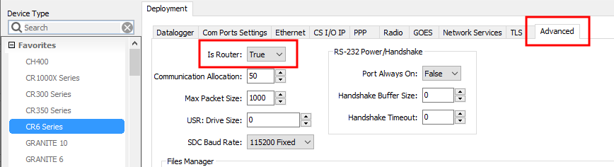
Click the Advanced sub-tab and set Is Router to True.
(Click image to expand/collapse display) -
Apply to save your changes.
Typically only the base data logger is configured as a router. Configuring multiple data loggers as routers may create unnecessary network traffic.
Add routing data logger to LoggerNet network
-
Using
LoggerNet Campbell Scientific's data logger support software for programming, communications, and data retrieval between data loggers and a computer., click Setup  and click the View menu to ensure you are in the Standard view.
 -
Click Add Root
 .
. -
Click ComPort, then PakBusPort (PakBus Loggers), then
-
Click Close.
-
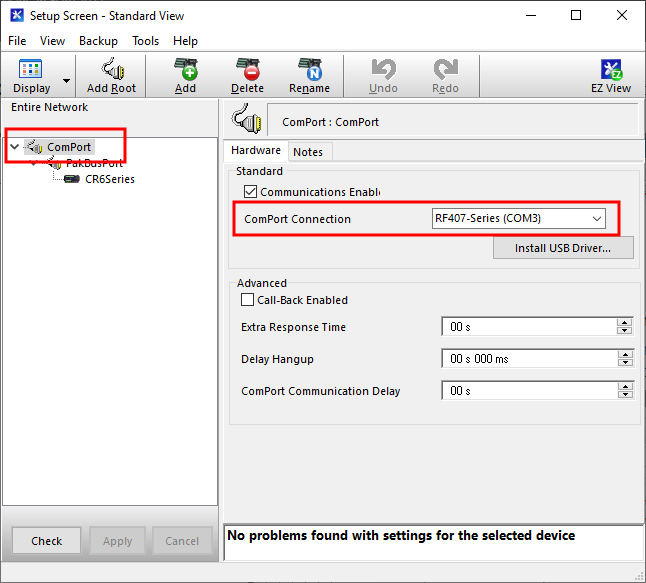
In the Entire Network pane on the left side of the window, select the ComPort.
-
On the Hardware tab on the right, click the ComPort Connection list and select the communications port assigned to the RF407-series radio.

(Click image to expand/collapse display) -
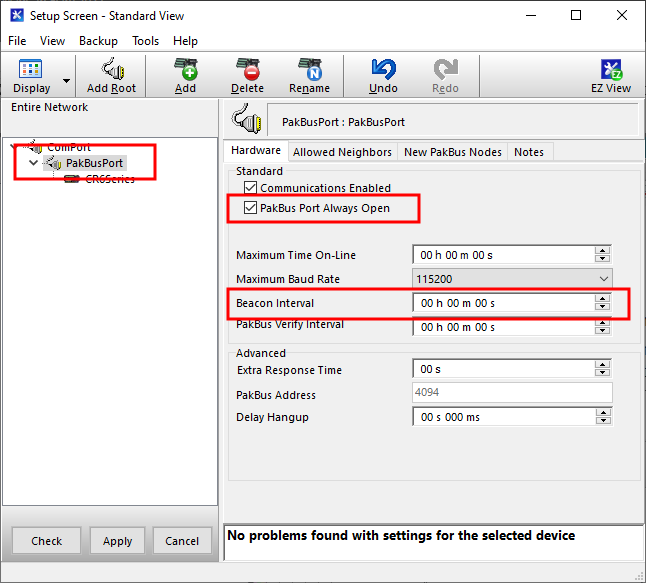
In the Entire Network pane on the left side of the window, select PakBusPort.
-
On the Hardware tab on the right, select the PakBus Port Always Open check box.
-
If you would like to prevent the possibility of LoggerNet communicating directly with any other data loggers in the network without going through the router, set the Beacon Interval to 00 h 00 m 00s.

(Click image to expand/collapse display) -
-
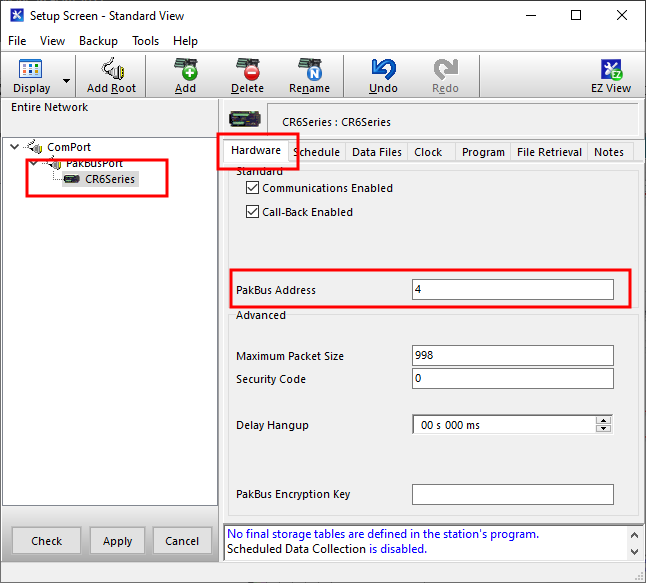
In the Entire Network pane on the left side of the window, select the router data logger
-
On the Hardware tab on the right, type the PakBus Address you assigned to the router data logger in Device Configuration Utility.

(Click image to expand/collapse display) -
Click Rename
 to provide the data logger a descriptive name.
 -
Apply to save your changes.
Configure remote (leaf) data loggers
Follow steps 1 – 6 in Configure the data logger acting as a router to assign a unique PakBus address to each leaf data logger. Do not configure leaf data loggers as routers.
Add leaf data loggers to the network
-
In the
LoggerNet Campbell Scientific's data logger support software for programming, communications, and data retrieval between data loggers and a computer. Standard Setup view (click the Setup option and click the View menu to ensure you are in the Standard view), right-click on the router data logger in the Entire Network pane on the left side of the window and select -
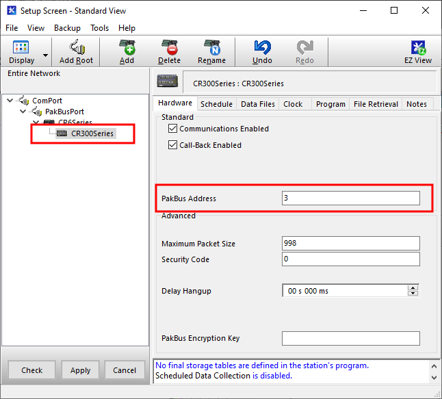
With the newly added data logger selected in the Entire Network pane, set the PakBus Address to the address that was assigned to the leaf data logger in Device Configuration Utility.

(Click image to expand/collapse display) -
Click Rename
to provide the data logger a descriptive name. -
Apply to save your changes.
-
Repeat these steps for each leaf data logger in the network.
If you experience problems with network communications, see Troubleshooting radio communications for assistance.
Using additional communications methods
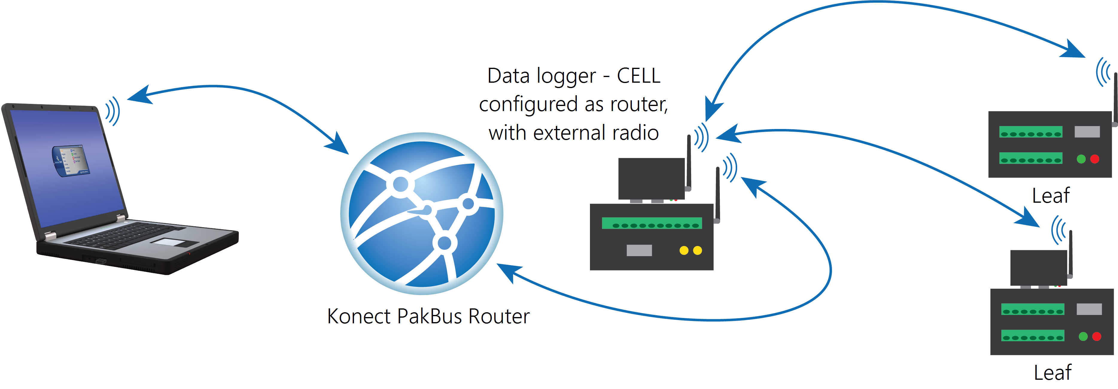
Using similar instructions, a RF407-series data logger can be used in a system with additional communications methods. For example, in the following image, the router RF407-series data logger communicates with LoggerNet through Konect PakBus Router. The router RF407-series data logger communicates with the leaf RF407-series data loggers over RF.
(Click image to expand/collapse display)
The RF portion of this network requires no changes to the hardware settings described in the previous procedure.
See the Konect Pakbus Router Getting Started Guide ![]() for more information on setting up that part of the network.
for more information on setting up that part of the network.