Data collection platform (DCP) installation
- Yagi antenna installation procedure:
-
Mount the Yagi antenna to a pole or mast by using the U-bolts included with the antenna mount.
-
Attach elements to boom.
NOTE:When attaching elements to the boom, make sure to place them such that the number of grooves on the element equals the number of dimples on the boom. For example, the element with four grooves should be placed at the spot on the boom with four dimples, and so forth.
-
Aim the Yagi antenna at the spacecraft; azimuth and elevation angle positions are included on the bracket label.
- GPS antenna installation procedure:
-
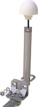
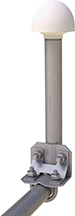
Connect the GPS cable to the GPS antenna.
-
Route the cable through the 0.75-inch IPS threaded pipe and insert the pipe into the GPS antenna.
-
Mount the 0.75-inch IPS threaded pipe to a crossarm by using the Nu-Rail® fitting or right-angle mounting kit.
 CAUTION:
The GPS antenna will not receive a GPS signal through steel roofs or steel walls. Concrete might also be a problem. Heavy foliage, snow, and ice will attenuate the GPS signal.
-
Mount the TX325, the power supply, and the data logger to the backplate of an enclosure.
-
Mount the enclosure and solar panel to the pole or tripod.
-
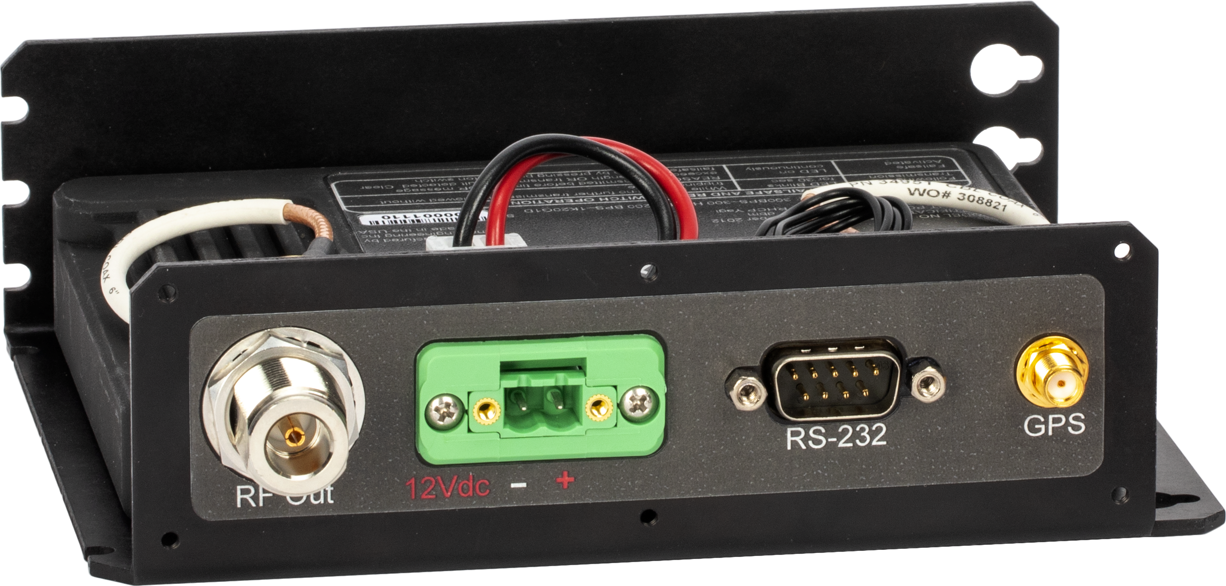
Connect the COAXNTN cable to the Yagi antenna. Route the COAXNTN cable through the enclosure conduit and connect it to the RF Out connector on the TX325 (TX325 connectors).
-
Route the GPS antenna cable through the enclosure conduit and connect it to the GPS connector on the TX325 (TX325 connectors).
-
Plug the green connector from the power supply to the green receptacle on the TX325.
CAUTION:The TX325 should never directly draw power from the data logger. The transmitter draws 2.5 A of power during transmission. The data logger can provide a maximum of 0.9 A over its 12 VDC terminals, which is insufficient. To avoid transmission issues, ensure that the TX325 power is directly connected to the charging regulator or the battery.
-
Connect the data logger to the TX325 RS-232 terminal.
-
Route the solar panel cable through the enclosure conduit and connect the red and black wires to the CHG terminals on the CH150, CH200, or CH201.