QuickStart
The SnowVue 10 Patch for Short Cut v4.4 v.1.0 is required for ShortCut versions 4.4 and older. This patch is available at www.campbellsci.com/snowvue10 ![]() .
.
A video that describes data logger programming using Short Cut is available at: www.campbellsci.com/videos/cr1000x-data logger-getting-started-program-part-3  . Short Cut is an easy way to program your data logger to measure the sensor and assign data logger wiring terminals. Short Cut is available as a download on www.campbellsci.com
 ![]() . It is included in installations of LoggerNet, RTDAQ, and PC400.
. It is included in installations of LoggerNet, RTDAQ, and PC400.
-
Open Short Cut and click Create New Program.
-
Double-click the data logger model.
-
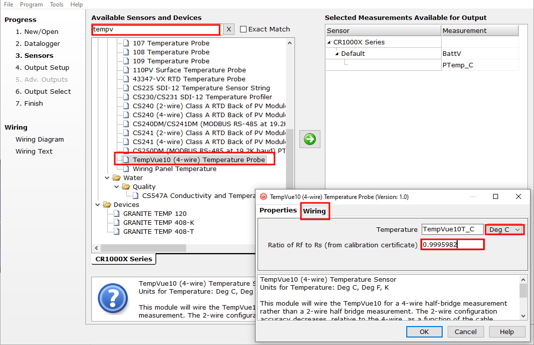
In the Available Sensors and Devices box, type

-
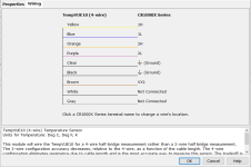
Click the Wiring tab to see how the temperature probe is to be wired to the data logger. Wire the probe accordingly, then click OK.
-
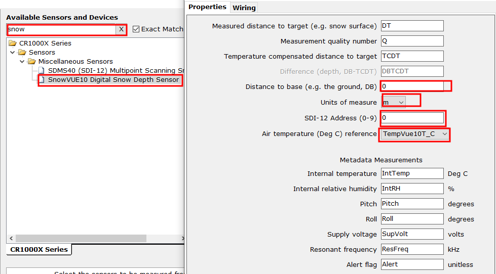
In the Available Sensors and Devices box, type SnowVue 10 or locate the sensor in the Sensors > Miscellaneous Sensors folder. Double-click

-
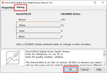
Click the Wiring tab to see how the sensor is to be wired to the data logger. Wire the sensor accordingly, then click OK.
-
Repeat steps five and six for other sensors, if necessary. Click Next.
-
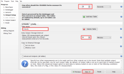
In Output Setup, type the scan rate, meaningful table names, and Data Output Storage Interval. Click Next. For this sensor, Campbell Scientific recommends a measurement rate between 20 and 60 seconds.
-
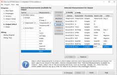
Select the desired output options.
-
Click Finish and save the program. Send the program to the data logger if the data logger is connected to the computer.
-
If the sensor is connected to the data logger, check the output of the sensor in the data display in LoggerNet, RTDAQ, or PC400 to make sure it is making reasonable measurements.