Base connectors

The SkyVue 8 has two connectors on its base. One connector (6 pins) is for communications; another connector (4 pins) provides power to the unit.

NOTE:

Tilting the unit provides better access to these connectors.

Connector layout

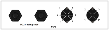
The function of the connector pins is shown in Function of the connector pins for the mains connector, Function of the connector pins for the blower/heater connector, and Function of the connector pins for the communications connector.

Function of the connector pins for the mains connector

Pin

Function

Color of supplied cable cores

1 Live Brown
2 Not connected NA
3 Neutral Blue
4 Earth Green/yellow


Function of the connector pins for the blower/heater connector

Pin

Function

Color of supplied cable cores

1 Neutral Black (1)
2 Fan + 12 VDC Black (2)
3 Thermistor Black (3)
4 Thermistor (0 V) Black (4)
5

Switched 230/115 VAC
high voltage heater

Black (5)
6

Switched 230/115 VAC
low voltage heater

Black (6)
E Earth Green/yellow


Function of the connector pins for the communications connector

Pin on connector on
SkyVue 8

Color of supplied cable cores

9-pin D connector

RS-232

RS-485 half duplex

RS-485 full duplex/
RS-422

1 Red 8 CTS (DCE) output B/D+ Y/TXD
non-inverting
2 Yellow 7 RTS (DCE) input   B/RXD
non-inverting
3 Green 5 Gnd    
4 Black     Gnd Gnd
5 White 2 RXD (DCE) output A/D– Z/TXD inverting
6 Blue 3 TXD (DCE) input   A/RXD inverting
E Screen