Schematic
RS-485 internal circuit diagram shows the internal configuration of the SDM‑SIO2R when configured in RS-485 or RS-422 full-duplex mode. This shows the internal resistors to aid users trying to test system interconnections and drive levels.
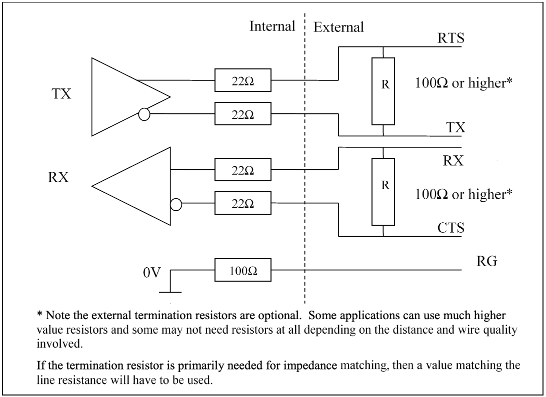
RG is for connecting the screen/ground of the data lines when in RS-485 mode; there is a 1 W 100 Ω resistor in series designed to limit any currents that may be induced due to a difference in ground potentials between the sensor and the SDM‑SIO2R.