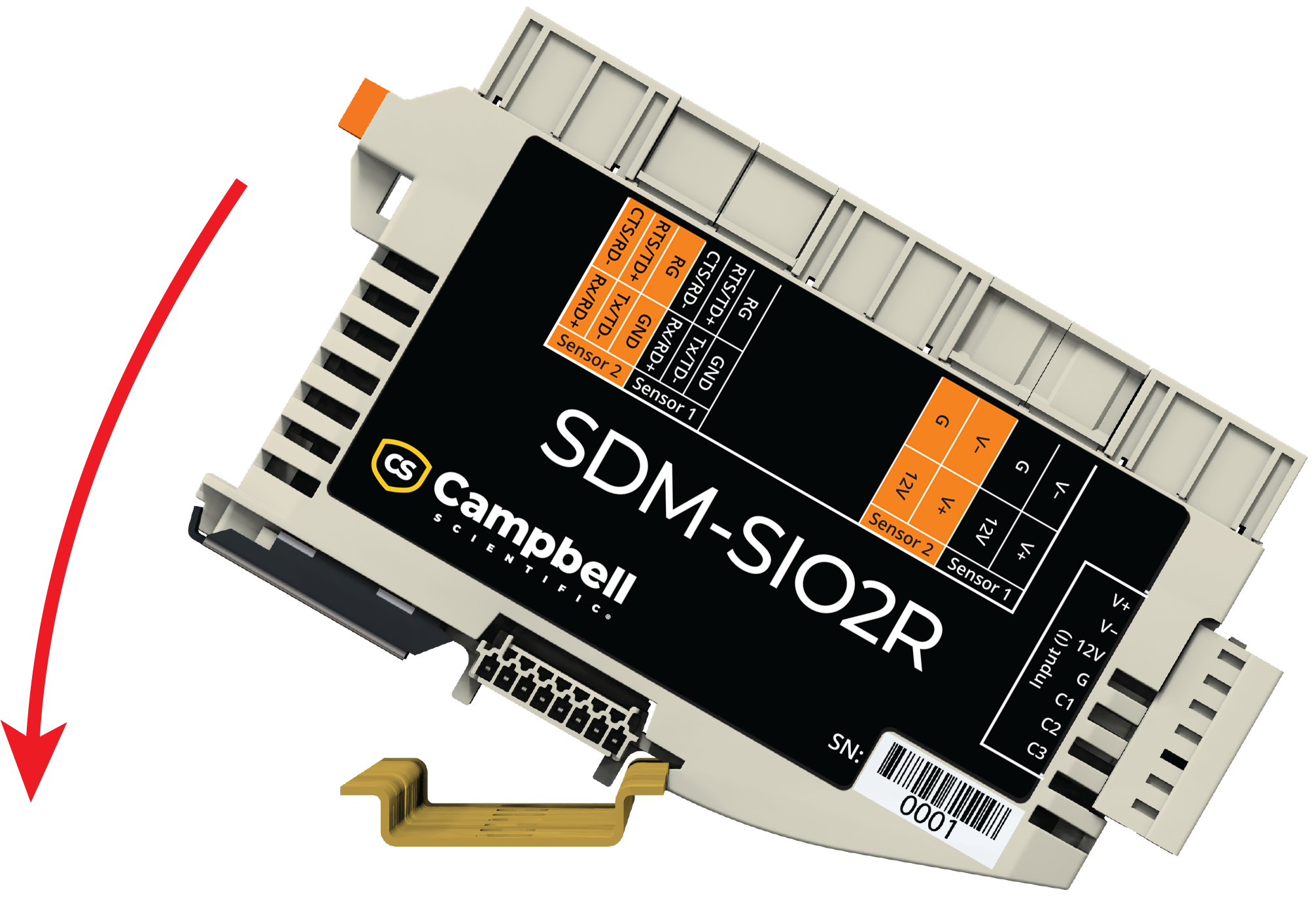
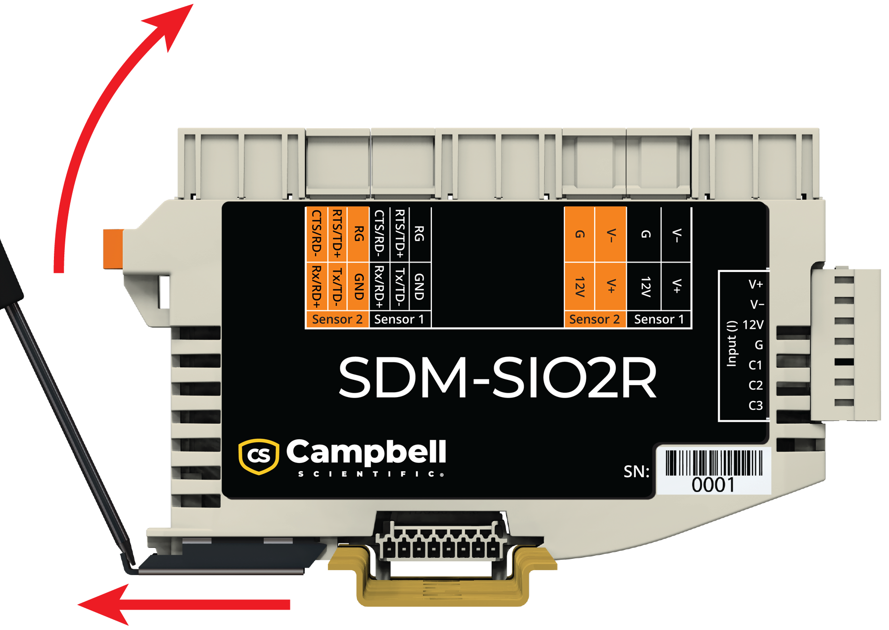
Mounting
The SDM‑SIO2R is designed to be installed in a dry, non-condensing environment.
CSI pn 39979 is the only DIN rail connector and bus that can be used. The warranty will be voided if a non-specified connector is used.
Ground path is through DIN rail clip. Ensure DIN rail is properly grounded.
All SDM‑SIO2Rs that are connected on the DIN rail will share a common bus.
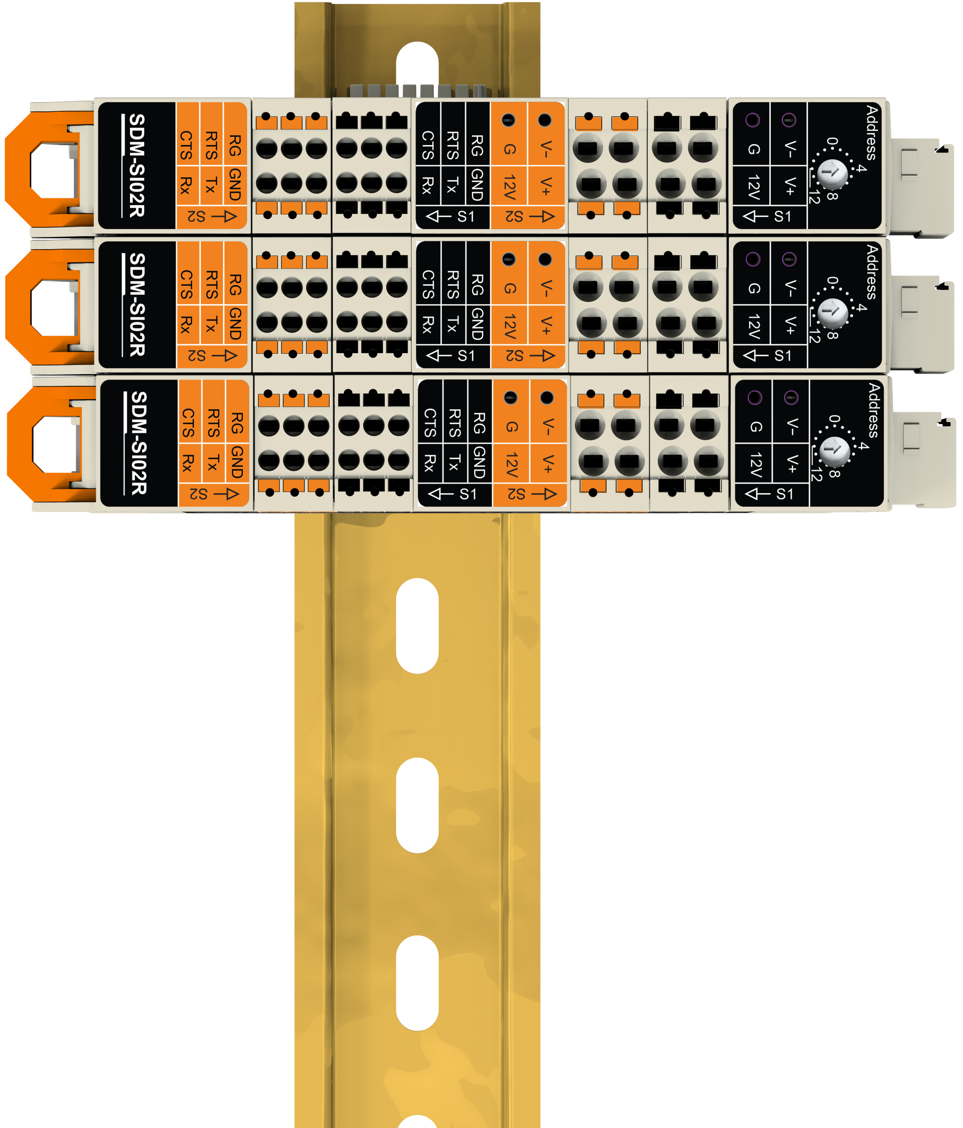
Multiple SDM‑SIO2Rs sharing a common bus
Keep SDM‑SIO2Rs apart to maintain separate buses.
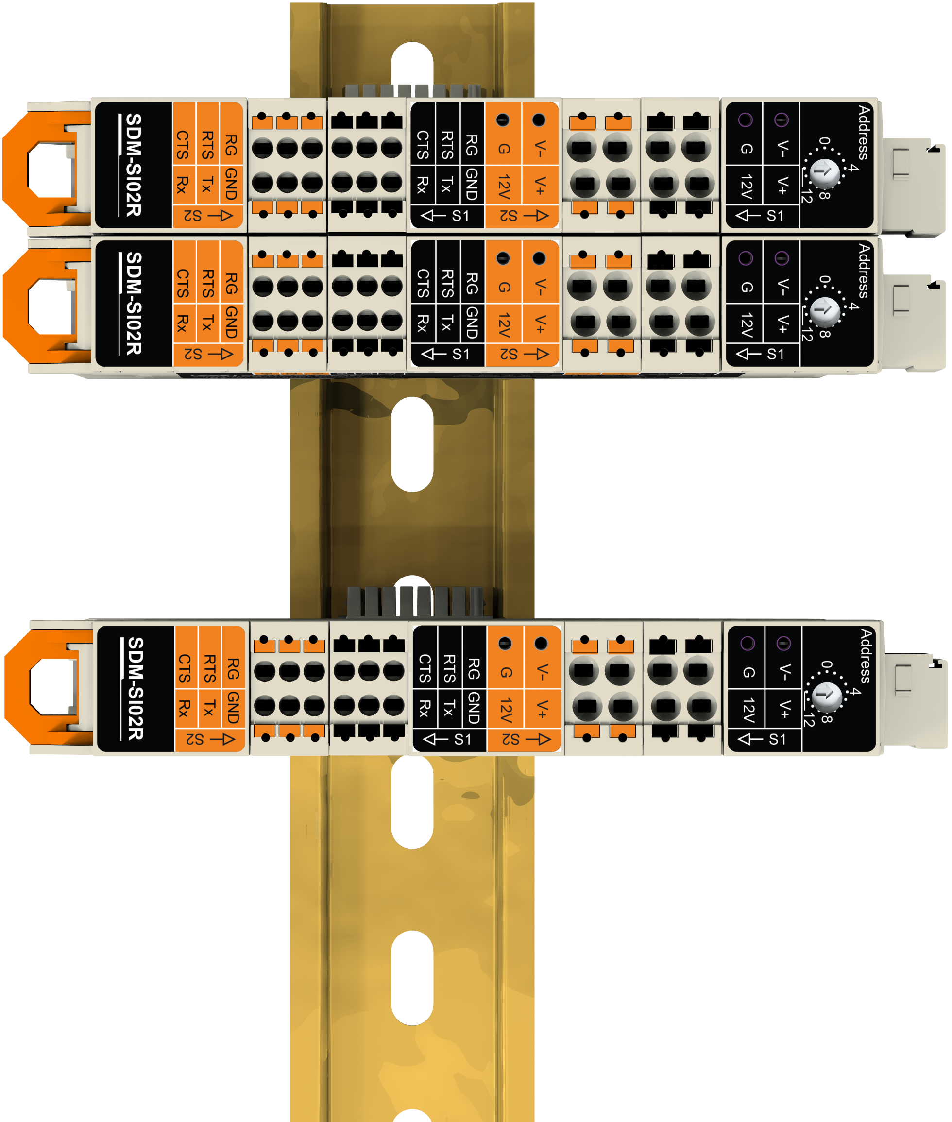
Multiple SDM‑SIO2Rs with separate buses
Before mounting, select and set the SDM address. The SDM address is set with a screwdriver. SDM address settings lists the possible SDM addresses and their relationships to the COMPort parameter in the SerialOpen() instruction.
There can be up to 8 SDM‑SIO2Rs on a single SDM bus. Each SDM‑SIO2R will need to be set to a unique address before they are powered. The SDM‑SIO2R has a single address switch. This sets the address of the first serial port of the module (sensor 1). The SDM address of the second serial port will follow sequentially from the port 1 address. For example, if the address switch is set to 4, sensor 1 has SDM address 4 and sensor 2 has SDM address 5. Since each SDM‑SIO2R on the bus takes up two SDM addresses, their address switches must be set with at least one address in between. If an address switch is set to “E” (SDM 14), only the first port of the SDM‑SIO2R is enabled. If any other equipment is present on the bus, whether an SDM‑SIO2R or other SDM device, the user will have to ensure their addresses are unique.
If the address switch is changed, the SDM‑SIO2R must be power cycled for the new address to take effect.
|
Rotary switch position |
SDM address |
SerialOpen() instruction |
|---|---|---|
|
0 |
0 |
32 |
|
1 |
1 |
33 |
|
2 |
2 |
34 |
|
3 |
3 |
35 |
|
4 |
4 |
36 |
|
5 |
5 |
37 |
|
6 |
6 |
38 |
|
7 |
7 |
39 |
|
8 |
8 |
40 |
|
9 |
9 |
41 |
|
|
10 |
42 |
|
|
11 |
43 |
|
|
12 |
44 |
|
|
13 |
45 |
|
|
14 |
46 |
|
|
151 |
471 |