Connection and wiring
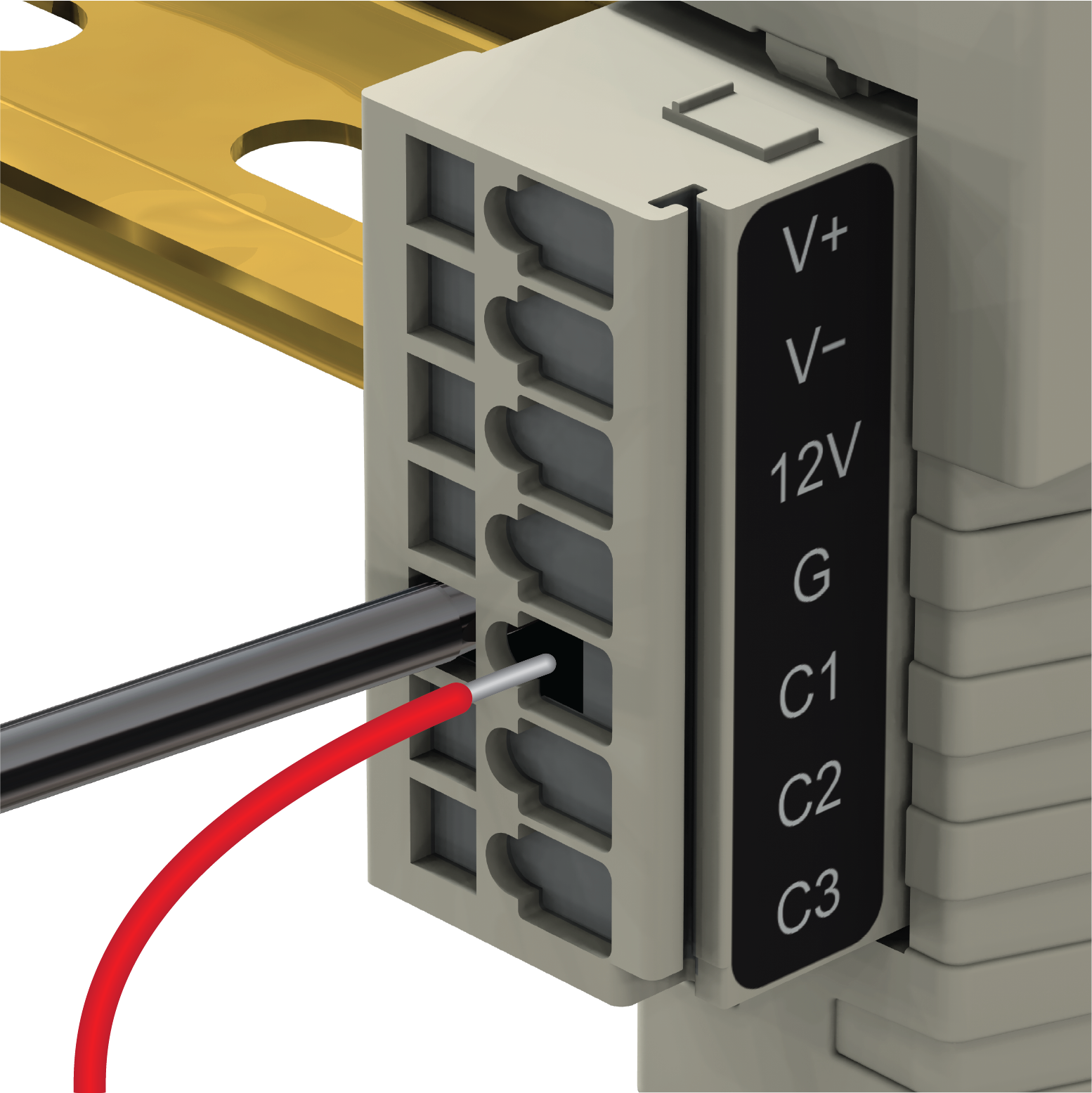
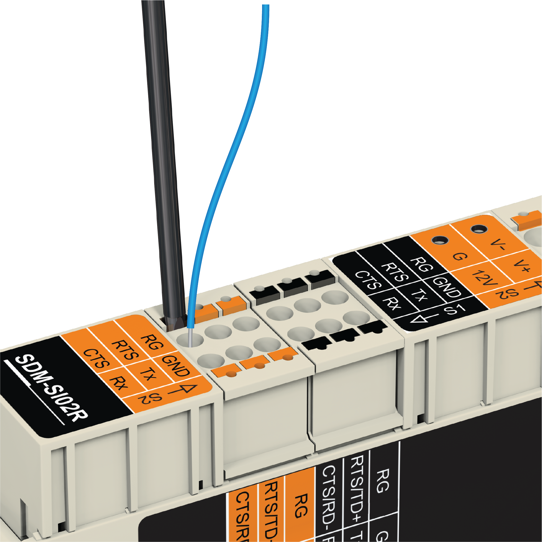
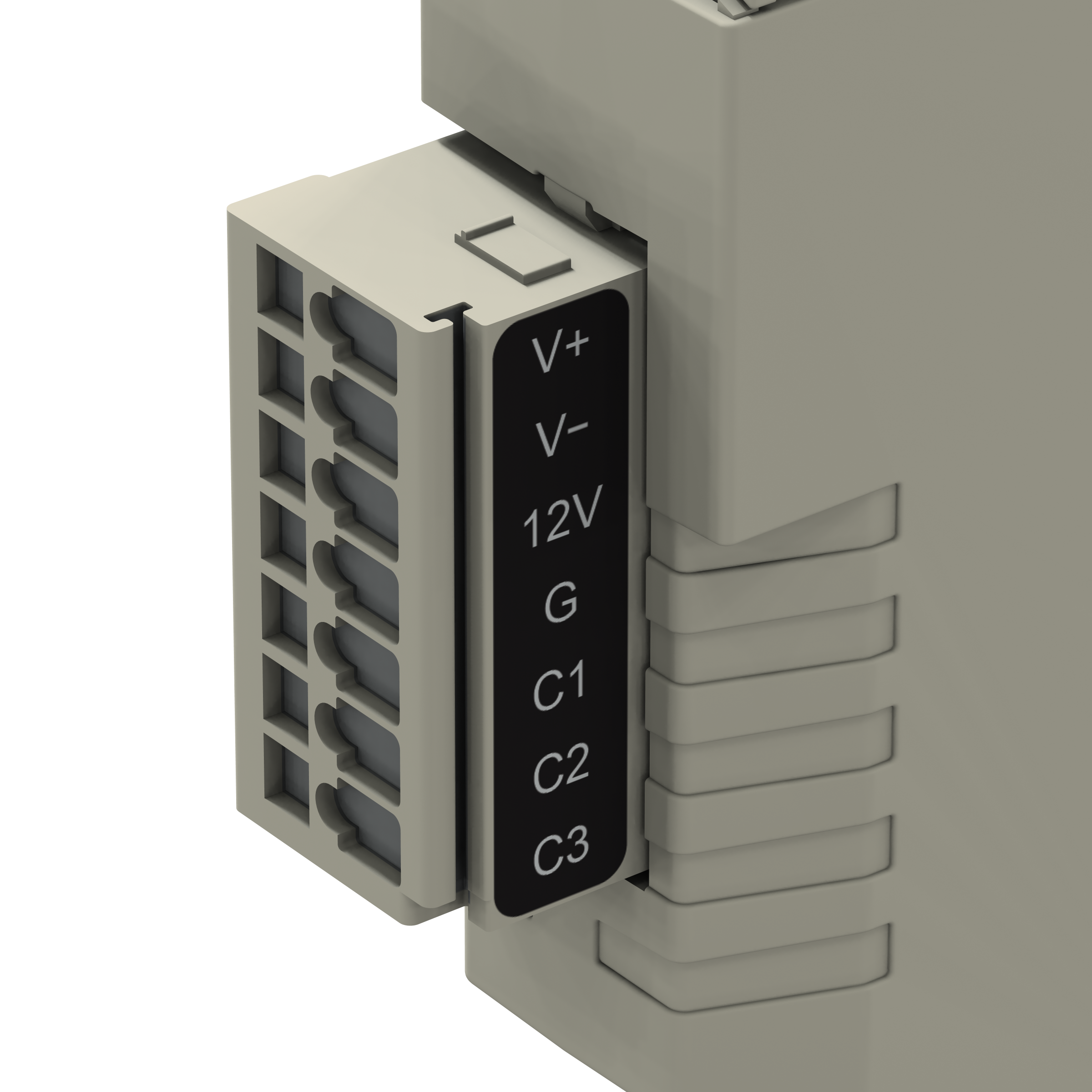
SDM‑SIO2R connections to the data logger are made via the Input connector. Strip wires 7 to 9 mm and twist. Open the clamp by inserting a small screwdriver into the small hole and prying away from the clamp. Insert the wire. Release the clamp and verify the clamp grips the wire rather than the plastic insulation. See Input connections.
If there is a need to insert more than one wire in each terminal, if using multi-strand wire, twist the conductors together first. If using solid wires, solder or crimp multiple pairs together before insertion.
Ferrules can be used for connections.
-
The SDM‑SIO2R Input connector can handle wire sizes ranging from 14-28 AWG.
-
The SDM‑SIO2R 6- Pin and 4-pin sensor communication connectors can handle wire sizes ranging from 16-24 AWG.
-
When using 20-24 AWG ferrules on the SDM‑SIO2R 6-pin communication connectors, longer ferrules must be used (for example, Campbell Scientific pn 40233).
-
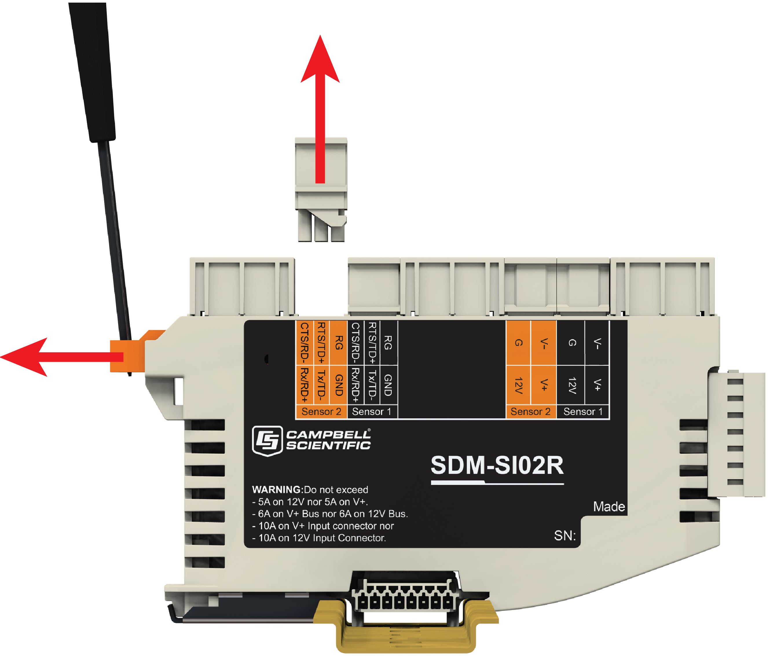
If necessary, a connector can be removed from the device by unlocking the slide bar. See Connector release slide bar.
The 12V power ground for the SDM‑SIO2R must be common ground with the data logger in order for the C1/C2/C3 communications to work.
The sensor with the highest current draw should be connected to the SDM‑SIO2R that is plugged into power and communications on the Input connector. It is recommended that this is the center SDM‑SIO2R in the system.
SDM‑SIO2R input terminal labels and functions shows all the input connections on the SDM‑SIO2R.
|
Power |
SDM |
|||||
|---|---|---|---|---|---|---|
| V+ | V- |
12V |
G |
C1 |
C2 |
C3 |
| 1 | 2 |
3 |
4 |
5 |
6 |
7 |
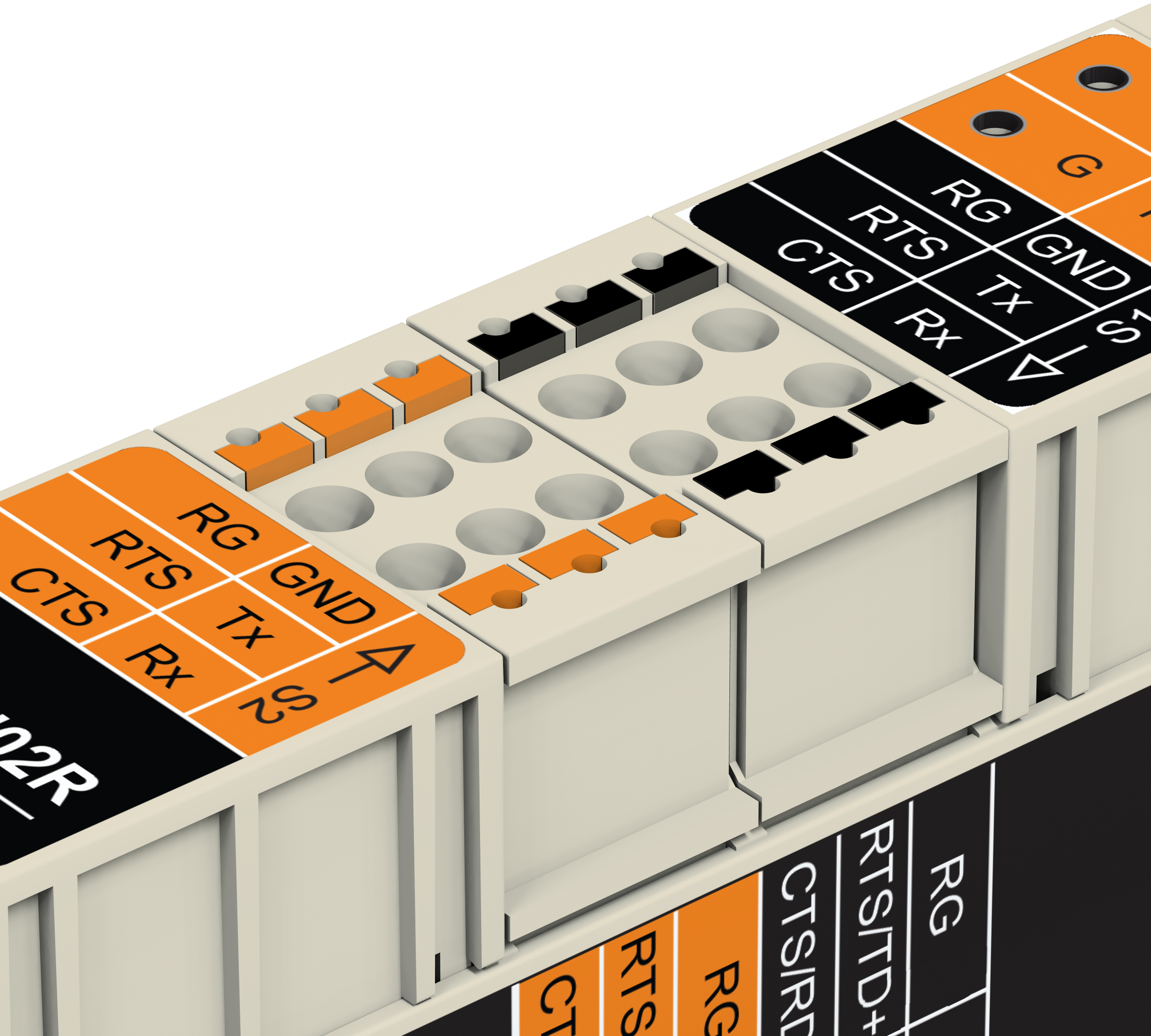
SDM‑SIO2R communication terminal labels and functions shows all the serial communication connections on the SDM‑SIO2R. Note that there are two communication connectors. One for Sensor 1 and one for Sensor 2.
|
Communication |
|||||
|---|---|---|---|---|---|
| RG | GND |
RTS |
Tx |
CTS |
Rx |
| 1 | 2 |
3 |
4 |
5 |
6 |
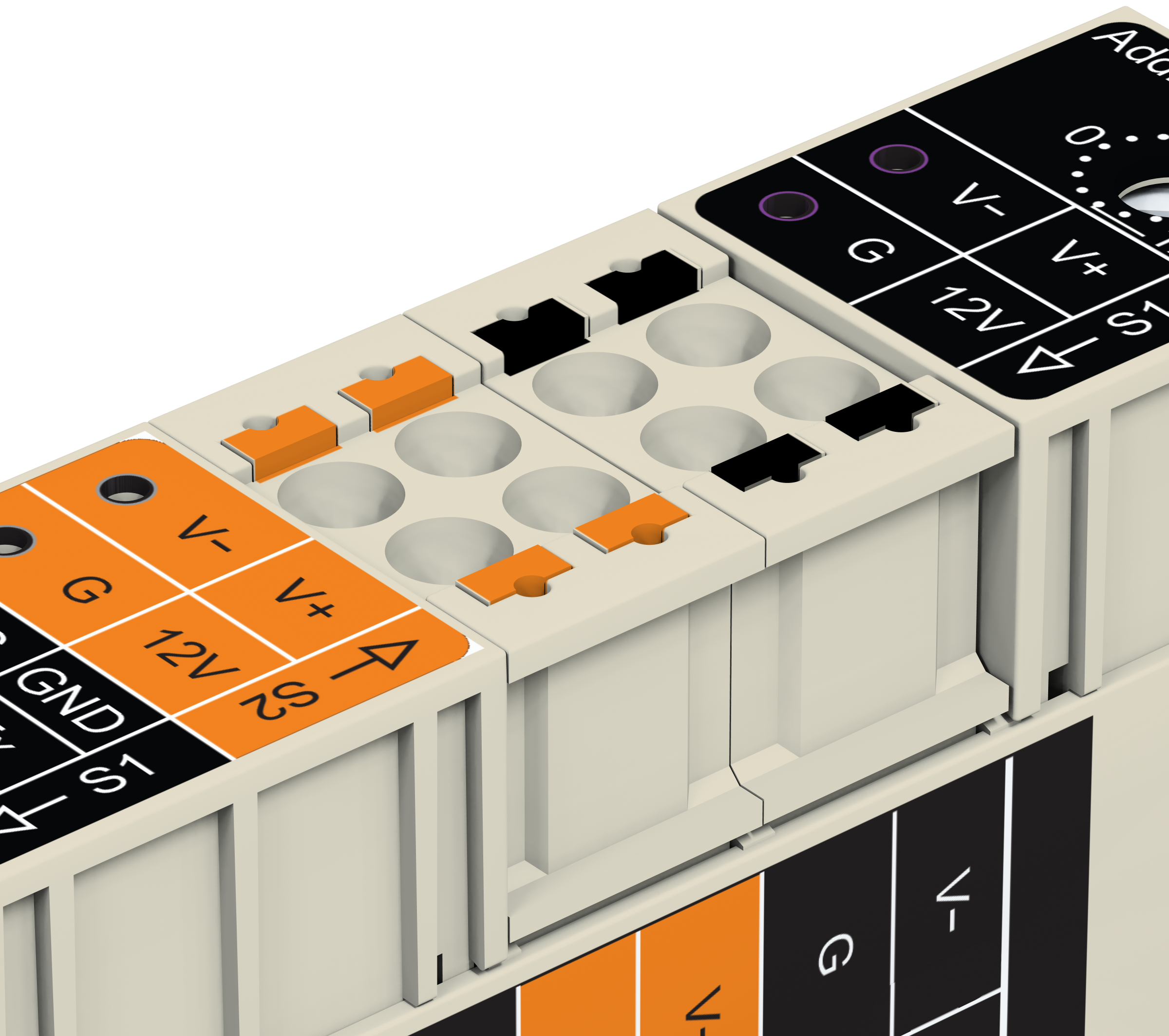
SDM‑SIO2R power pass-through terminal labels and functions shows all the power pass-through connections on the SDM‑SIO2R. Note that there are two power pass-through connectors. One for Sensor 1 and one for Sensor 2.
|
Power pass-through |
|||
|---|---|---|---|
| V- | V+ |
G |
12V |
| 1 | 2 |
3 |
4 |
|
Pin |
Case text |
Connection to |
Description |
|---|---|---|---|
| 1 | V+ |
Power supplies |
Power supply 0-30V AC or DC |
| 2 | V- | Power supply return 0-30V AC or DC | |
|
3 |
12V |
Power supply |
|
|
4 |
G |
Power supply ground |
|
|
5 |
C1 |
Data logger |
SDM_Data |
|
6 |
C2 |
SDM_Clock |
|
|
7 |
C3 |
SDM_DataEnable |
|
|
Pin |
Case text (RS-232 Function) |
RS-485 Function |
Connection to |
Description |
|---|---|---|---|---|
|
1 |
RG1 |
Sensors
Note that all of the sensor connections are repeated on two connectors: Sensor 1 and Sensor 2
|
RG – RS‑485 ground. Connected to G via 100 Ω 1 W resistor. |
|
|
2 |
GND2 |
GND - ground for RS-232 communications |
||
|
3 |
RTS |
TD+ |
RS‑232 RTS. RS‑485 half duplex non-inverting. RS‑485 full duplex outgoing. |
|
|
4 |
Tx |
TD– |
RS‑232 transmit. RS‑485 half duplex inverting. RS‑485 full duplex outgoing. |
|
|
5 |
Rx |
RD+ |
RS‑232 receive. RS‑485 receiver non-inverting. RS‑485 full duplex incoming. |
|
|
6 |
CTS |
RD– |
RS-232 CTS. RS‑485 receiver inverting. RS‑485 full duplex incoming. |
|
| 1 | V- | AC or DC voltage source return from power supply | ||
| 2 | V+ | AC or DC voltage source from power supply | ||
| 3 | G | DC ground from power supply | ||
| 4 | 12V | DC voltage source from power supply | ||
The connection of the wires to the remote serial device
If possible, use screened cable for connecting the SDM‑SIO2R to remote sensors or devices. Check the manual of the device for details on where to connect the screen for maximum effectiveness.
RS-422 mode is functionally the same as RS-485 mode except the connection is limited to a point-to-point system. Connections and programming for RS-422 are otherwise identical to full-duplex RS-485.
When operating in RS-232 mode, the SDM‑SIO2R also supports hardware handshaking.
Wiring examples for connecting the SDM‑SIO2R provides examples of different connection schemes for the serial devices. Further discussion of different modes of operation is given in Operation.