Operation and maintenance
Protect the data logger and RV50(X) from humidity and moisture. When humidity levels reach the dewpoint, condensation occurs, and damage to electronics can result. Adequate desiccant should be placed in instrumentation enclosure to provide protection, and control humidity. Desiccant should be changed periodically.
Ports
The RS-232 port is the main port used with Campbell Scientific data loggers. Its function is described throughout this manual.
The USB port is not used in Campbell Scientific applications.
The Ethernet port may be used in place of PPP Mode to get to the IP stack of the data logger. However, this method comes with higher current drain for both the module and the data logger. See Using the RV50(X) Ethernet port for more information.
LED indicator lights
When your RV50(X) is connected to power and an antenna, there is a specific pattern to the lights to indicate its operation mode as described in the following table:
|
LED indicator lights |
|||
|---|---|---|---|
| LED | Color / Pattern | Description | LED Power Saving Mode |
| Power | Off | No power or input voltage ≥ 36 VDC or ≤ 7 VDC | |
| Solid Green | Power is present. | ||
| Green with Amber Flash | Power is present and the modem has a GPS fix. | ||
| Solid Red | Standby mode | ||
| Flashing Green | When you press the reset button, flashing green indicates when to release the reset button to reboot the modem. | ||
| Flashing Red | When you press the reset button, flashing red indicates when to release the reset button to reset the modem to the factory default settings. | ||
| Flashing Amber | When you press the reset button for more than 20 seconds, flashing amber indicates when to release the reset button to enter Recovery mode. | ||
| Signal | Solid Green | Good signal (equivalent to 4–5 bars) | Off |
| Solid Amber | Fair signal (equivalent to 2–3 bars) | Off | |
| Flashing Amber |
Poor signal (equivalent to 1 bar) |
||
| Flashing Red |
Inadequate (equivalent to 0 bars)
|
||
| NOTE: The quality of the signal strength is measured using the appropriate parameters for the radio technology in use. | |||
| Network | Solid Green | Connected to an LTE network | Off |
| Solid Amber |
Connected to a 3G network or 2G network (RV50 only) |
Off | |
| Flashing Green | Connecting to the network | ||
| Flashing Red | No network available | ||
| Flashing Red / Amber | Network Operator Switching is enabled, but the modem is unable to locate the required firmware. For more information, refer to the ALEOS Software Configuration User Guide (Admin chapter) from the Sierra Wireless website. | ||
| Activity | Flashing Green | Traffic is being transmitted or received over the WAN interface. | |
| Flashing Red | Traffic is being transmitted or received over the serial port. This behavior only appears if the RV50(X) is configured to display it. For more information, refer to the ALEOS Software Configuration Guide (Serial chapter) from the Sierra Wireless website. | ||
| Flashing Amber | Traffic is being transmitted or received over both the WAN interface and the serial port. This behavior only appears if the RV50(X) is configured to display it. Refer to the ALEOS Software Configuration Guide (Serial chapter) from the Sierra Wireless website. | ||
| ALL | Green LED chase | Radio module reconfiguration/firmware update or Network Operator Switching is in progress. | |
| Amber LED chase | Firmware update is in progress. | ||
| Solid Amber | Firmware update complete (all LEDs are amber except the Power LED) | ||
| Red LED chase | The modem is in Recovery mode. | ||
Signal strength and quality
Both signal strength and quality contribute to successful cellular data communications. The factors that influence signal strength and quality include but are not limited to:
- proximity to the cellular tower
- tower load
- competing signals
- physical barriers (mountains, buildings, vegetation)
- weather
Because signal strength and quality can vary due to many factors, they may not give a true indication of communications performance or range. However, they can be useful for activities such as:
- determining the optimal direction to aim a Yagi antenna
- determining the effects of antenna height and location
- trying alternate Yagi antenna (reflective) paths
- seeing the effect of vegetation and weather over time
Signal strength
Signal strength is how strong the received signal is. The closer your RV50(X) is to the cellular tower, the more signal the antenna will pick up. Signal strengths are lower the farther away from the tower the RV50(X) is.
For 3G networks, signal strength is reported as RSSl (Received Signal Strength Indicator). For 4G, it is RSRP (Reference Signal Received Power).
Signal strength units are –dBm; –70 is a stronger signal than –100.
- -78: good
- -78 to -93: fair
- - 94 to -102: poor
- less than -103: inadequate
Signal quality
Signal quality shows how much interference there is between the cellular tower and RV50(X), or how noisy a band is. Cellular signal noise comes from reflections, ghosting and other interference. Better signal quality is an indicator of more successful communications during precipitation events such as rain and snow.
For 3G networks, signal quality is ECIO (Energy to Interference Ratio). For 4G, this is RSRQ (Reference Signal Received Quality).
Signal quality units are –dBm; 0 is a better signal than –10.
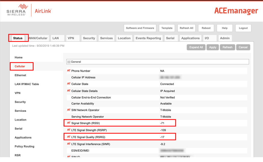
Find your module signal strength and quality through ACEmanager. Click Status > Cellular and look for Signal Strength (RSSI) and Signal Quality (RSRQ).
Rebooting the RV50(X)
There are two methods to reboot the RV50(X):
- On the RV50(X), press the Reset button for 1–5 seconds. (Release the button when the Power LED flashes green.)
- In ACEmanager, click the Reboot button on the toolbar.
Reset the RV50(X) to factory default settings
There are two methods to reset the RV50(X) to the factory default settings:
- On the RV50(X), press the Reset button for more than 5 seconds. (Release the button when the Power LED flashes red.) Once the LEDs resume their normal operating behavior, the reset is complete.
- In ACEmanager, go to Admin > Advanced and click the Reset to Factory Default button.
Recovery mode
If the RV50(X) fails to boot properly, it automatically enters recovery mode. If the RV50(X) is unresponsive to ACEmanager input and AT commands, it can manually be put into recovery mode.Recovery mode enables you to update the RV50(X) firmware and return it to working order.
To enter Recovery mode manually:
- Press the Reset button for more than 20 seconds. (Release the button when the Power LED flashes amber.)
To recover the router:
- Update the firmware using the Recovery mode interface. Once the new version is successfully uploaded and installed, the RV50(X) will reboot and exit Recovery mode. When the process is complete, the ACEmanager login screen will appear.
Reload the RV50(X) firmware and templates after the Recovery.
To exit Recovery mode, if it has been inadvertently entered, do one of the following:
- Press the RV50(X) Reset button.
- Click Reboot on the ACEmanager Recovery screen.
- Wait 10 minutes. If no action is taken within 10 minutes of the module entering Recovery mode (for example, if the Recovery screen has not been loaded by the web browser), it automatically reboots and exits Recovery mode.