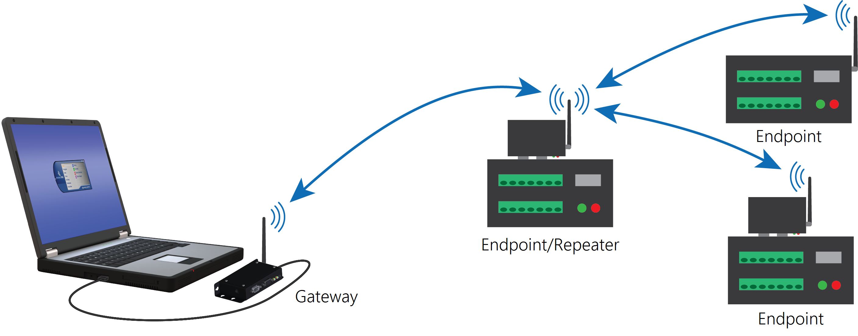
RF451/RF452 communications with multiple data loggers using one repeater
This type of network configuration is useful for communicating around an obstacle, such as a hill or building, or to reach longer distances.
The following table summarizes the hardware settings for this type of network.
|
RF451/RF452 settings for RF451/RF452 communications with multiple data loggers using one repeater |
|||
|---|---|---|---|
|
|
Gateway |
Endpoint/repeater |
Endpoint(s) |
|
Hardware |
RF451/RF452 connected to computer running LoggerNet |
RF451/RF452 connected to data logger CS I/O port |
RF451/RF452 connected to data logger CS I/O port |
|
PakBus Address |
4094 |
2 |
3 |
|
Keep all factory default settings except: |
|||
|
Active Interface |
USB or RS-232 (to match how LoggerNet will be communicating with the radio) |
CS I/O SDC (with SDC Address set to an unused SDC address on the data logger) |
CS I/O SDC (with SDC Address set to an unused SDC address on the data logger) |
|
Radio Operation Mode |
Gateway |
Endpoint/Repeater |
Endpoint |
|
Repeaters Used |
Yes, select box |
Yes, select box |
Yes, select box |
|
Network ID |
1726 (yours may be different) |
1726 (yours may be different) |
1726 (yours may be different) |
|
Frequency Key |
1 (yours may be different) |
1 (yours may be different) |
1 (yours may be different) |
|
Radio ID |
4094 (to match LoggerNet PakBus address) |
2 (to match data logger PakBus address)1 |
3 (to match data logger PakBus address)1 |
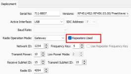
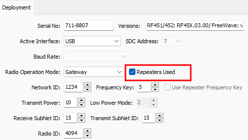
Configuring the RF451/RF452 radio connected to the computer
Configure the RF451/RF452 radio connected to the computer (see previous image for reference).
-
Ensure your RF451/RF452 radio is connected to an antenna before applying power.
-
Using Device Configuration Utility, connect to the RF451/RF452 radio.
-
On the Deployment tab, set the Active Interface to USB or RS-232 (depending on how your computer will be connected to the radio).
-
Set the Radio Operation Mode to Gateway. In the Network ID box, type a unique number between 0 and 4095 (excluding 255). This is used to communicate with RF451/RF452 devices in the network. Make note of this number. All radios in the network require the same Network ID.
-
In the Frequency Key box, type a number between 0 and 14, and make note of this number. Generally, all radios in the nework will have the same Frequency Key.
-
Select the Repeaters Used box.
-
Apply to save your changes.
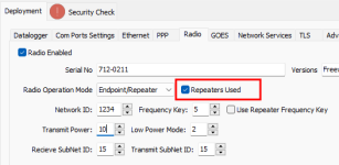
Configuring the data logger acting as a repeater
- Ensure your RF451/RF452 radio is connected to an antenna before applying power.
-
Supply power to the data logger. If connecting via USB for the first time, you must first install USB drivers by using Device Configuration Utility (select your data logger, then on the main page, click Install USB Driver). Alternately, you can install the USB drivers using EZ Setup.
-
Using Device Configuration Utility, connect to the RF451/RF452 data logger.
-
Click the Radio sub-tab and select the Repeaters Used box.
-
Also on the Radio sub-tab, set the Radio Operation Mode to Endpoint/Repeater. In the Network ID box, type the same number set in the previous instruction Configuring the RF451/RF452 radio connected to the computer.
-
In the Frequency Key box, type the same number set in the previous instruction.
-
Apply to save your changes.

Adding the endpoint/repeater data logger to the LoggerNet network
To add the repeater data logger to the LoggerNet network, follow the instructions found in Setting up communications between the RF451/RF452 data logger and the computer.
Adding endpoint data loggers to the network
-
In the LoggerNet Standard Setup view (click Setup
 and then the View menu to ensure you are in the Standard view), right-click on the repeater data logger in the Entire Network pane on the left side of the window and select your data logger model such as CR6Series.
 -
With the newly added data logger selected in the Entire Network pane, set the PakBus Address to the address that was assigned to the endpoint data logger in Device Configuration Utility.
-
Click Rename
 to provide the data logger a descriptive name.
 -
Apply to save your changes.
-
Repeat these steps for each endpoint data logger in the network.
Using additional communications methods
Using similar instructions, an RF451/RF452 data logger can be used in a system with additional communications methods. For example, in the following image, the router RF451/RF452 data logger communicates with LoggerNet through Konect PakBus Router. The router RF451/RF452 data logger communicates with the endpoint RF451/RF452 data loggers over RF.
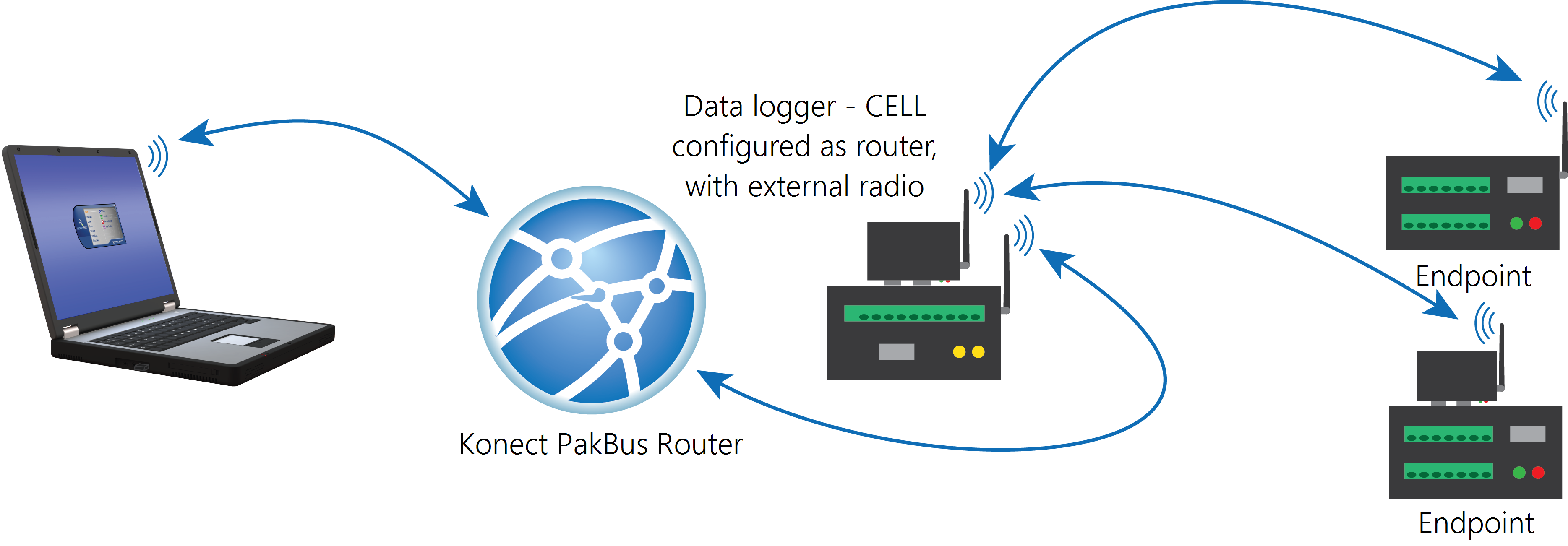
The RF portion of this network requires no changes to the hardware settings described in the previous procedure.
See the Konect Pakbus Router Getting Started Guide ![]() for more information on setting up that part of the network.
for more information on setting up that part of the network.