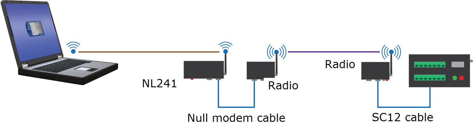
NL241 with radio network
This type of network is useful when the data logger is not located close enough to
Configure the NL241 as a PakBus router
Out of the box, the NL241 is configured for operation as a PakBus router. You may not need to make any changes. The following steps provide information about these default settings.
-
Connect to the NL241 in Device Configuration Utility.
-
On the NL241 tab, set Bridge Mode to disable.
-
If a dynamic address is to be used, the network information acquired via DHCP can be seen on the NL241 tab under Status. The Status box also displays the MAC address of the NL241.
-
To enter a static IP address, select disable in the Use DHCP field. Then input the IP Address, Network Mask, and Default Gateway. These values can be provided by your network administrator.
-
On the RS-232 tab:
-
Set Configuration to PakBus.
-
Set Baud Rate to baud rate of attached radio. Generally this is 115200 (default).
-
Set Beacon Interval to 60 (seconds) and Verify Interval to 0. If you want to restrict communications paths, use the PakBus Neighbors Allowed setting to specify allowed neighbor addresses.
-
-
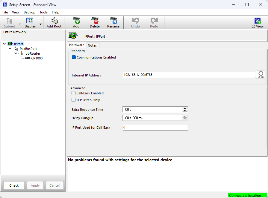
On the Network Services tab, make note of the PakBus/TCP Service Port. The default PakBus/TCP Service Port is 6785. Unless firewall issues exist, it is not necessary to change the port from its default value. This port number must match the port number entered in LoggerNet Setup after the IP address. See Setup LoggerNet.
Configure radio connected to the NL241
Using a USB cable, connect to the radio that will be connected to the NL241. Either an RF407-series or RF451/452 can be used. See those product manuals for additional details.
RF451/452
-
Connect to the radio in Device Configuration Utility.
-
Click the Factory Defaults button at the bottom of the Deployment window.
-
On the Deployment tab set:
-
Active Interface to RS-232
-
Radio Operation Mode to Gateway (previously called Master)
NOTE:There can only be one Gateway in an RF451/452 network.
-
-
Click Apply to save the changes.
Configure radio connected to the data logger
-
Using an SC12 cable, connect the data logger CS I/O port to the radio CS I/O port.
-
Connect a USB cable between a USB port on your computer and the radio USB port.
RF451/452
-
Connect to the radio in Device Configuration Utility.
-
Click the Factory Defaults button at the bottom of the Deployment window.
-
On the Deployment tab, keep the defaults and confirm:
-
Active Interface is CS I/O SDC
-
SDC Addres is 7
-
Radio Operation Mode is Endpoint (previously called Slave)
-
-
Click Apply to save the changes.
Configure the data logger
-
Connect to the data logger in Device Configuration Utility.
-
Click the Factory Defaults button at the bottom of the Deployment window.
-
On the Com Ports Settings tab set:
-
ComPort to CS I/O SDC7
-
Beacon Interval to 60 (seconds)
-
-
Click Apply to save the changes and then close Device Configuration Utility.
Setup LoggerNet
-
In the LoggerNet Setup screen, click Add Root and select IPPort. Enter the NL241 IP address and port number. The IP address and port number are input on the same line separated by a colon. IPv6 addresses will need to be enclosed in square brackets when specifying a port number. An IPv4 address may look like 192.168.1.100:6785. An IPv6 address may look like [2001:db8::1234:5678]:6785. A fully qualified host name entry may look like yourlogger.com:6785.
-
Add PakBusPort (PakBus Loggers).
-
Add a PakBus Router (pbRouter). Enter the PakBus address of the NL241. The NL241 default PakBus address is 678. Click Close.
-
Add the data logger and enter its PakBus address.
-
Click Apply to save the changes.
-
You are now ready to connect to your data logger using LoggerNet. Select Main and Connect on the LoggerNet toolbar, select the data logger from the Stations list, then Connect. From there, you can view and collect data, or manage data logger settings.