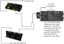
Phone to MD485 network
It is possible to access an MD485 network via telephone when the network is miles from the computer. See Telephone to MD485 conversion.
A Campbell Scientific Model COM220 Telephone Modem is used in conjunction with a Model PS150 Power Supply and A100 Null Modem Adapter to communicate with an MD485. The COM220 and the MD485 are both supplied with a 9 pin SC12 cable suitable for connection to the A100. The PS150 provides 5 and 12 volts for system operation and the A100 performs the function of a null modem (the COM220 and MD485 are both "modem" devices).
The telephone to MD485 Network using a PS150 with A100 may be done with Transparent Communications, but is not possible with PakBus networking. Connection to a single PakBus Data logger is still possible with Transparent Communications. PakBus networking can be done by using a data logger in place of the PS150/A100 for routing.
Where a phone to MD485 base is desired, the following configurations will provide point-to-point or point-to-multipoint communications.
-
HARDWARE REQUIREMENTS
-
MD485s
-
COM220
-
PS150 with A100
-
Transformer or solar panel
-
Three SC12 cables (one included with each MD485 and one with COM220)
-
CABLE2TP cable
-
-
TRANSPARENT COMMUNICATIONS (POINT-TO-POINT)
Computer-Modem---COM220-PS150 with A100-MD485---MD485-DL
LoggerNet Setup
-
Setup:
ComPort_1
PhoneBase
PhoneRemote
PakBus Port
CR1000X
-
ComPort_1 – default settings
-
PhoneBase
-
Modem Type – specify computer phone modem
-
Maximum Baud Rate – 9600
-
Extra Response Time – 0 s
-
-
PhoneRemote – input base site phone number
-
PakBus Port – defaults
-
CR1000X – default settings, schedule collections as desired
MD485 Configuration
-
Base MD485
-
Active Ports – CS I/O and RS-485
-
Protocol Configuration – Transparent Communications
-
CS I/O Mode – ME Master
-
RS-485 Port Configuration – Desired baud rate
-
-
Remote MD485
-
Active Ports – CS I/O and RS-485
-
Protocol Configuration – Transparent Communications
-
CS I/O Mode – Modem Enable
-
RS-485 Port Configuration – Desired baud rate
-
-
-
HARDWARE
After configuring LoggerNet and the MD485s, you are ready to set up hardware. The A100 null modem connectors (it’s not important which connector goes to which unit) connect using SC12 cables to the COM220 and the base MD485 CS I/O port. Connect the site phone line to COM220. Connect power to PS150. When you turn on the PS150 supply, the MD485 receives 12 V power and you will see the LEDs light in their power-up sequence.
Remote MD485s normally connect to data logger CS I/O ports via SC12 cables. Powering up the data logger will start the MD485 operating. Connect the CABLE2TP cable between the RS-485 ports of the base and remote MD485s and you are ready to connect to the data logger.
