TD-RF Quality Report
An RF modem primarily functions as an interface bridging two distinctly different modes of data transport; the wired medium of dataloggers and PCs, and the wireless medium of RF transceivers. The RF modem accomplishes this by converting the serial data stream from the wired medium into a waveform of proper amplitude and frequency for driving the FM modulator circuits of the RF transceiver, and vice versa.
In a process known as line coding, the RF modem encodes the binary data from the wired data stream onto a 3 KHz waveform. The line coding utilized in CSI’s TD-RF modems is called Miller Encoding. This encoding scheme employs a method of differentiating the binary “1s” and “0s” of the data stream based on the timing of transitions in the waveform from one level to another within the bit period (approximately 333 microseconds for a 3 KHz bit rate). A binary “1” is represented by a level transition occurring in the middle of the bit period. A binary “0” is represented by either there being no transition occurring within the bit period or, in the case of consecutive “0”s, the transition occurs at the end of the bit period.
In order to properly decode the encoded data from a received signal, one must precisely detect when the level transitions are occurring in relation to the middle and end of the bit period; the T1 and T2 transition points respectively. The OS in the RF modem does this by establishing a detection window centered about the time a transition is expected to occur. The detection window is 204 units wide, so the optimal transition timing would occur in the center of the window; unit 102. In the real world, the optimal transition timing is not likely to occur that often so there will always be some deviation to where the transitions occurs within the detection window. The more noisy the received signal, the greater the deviations. If the transition occurs outside the detection window, the proper bit will not be detected and a data error will occur. The demodulated data stream and the associated detection windows for the T1 and T2 transition points are illustrated in the graphic below.
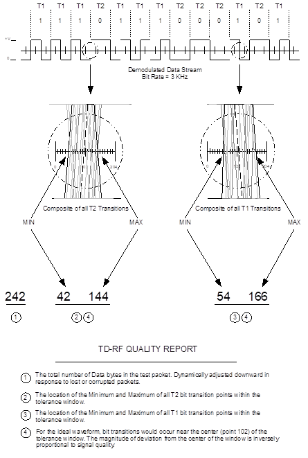
The information recorded in the TD-RF Quality Report includes the location of the maximum and minimum transition point for the T1 and T2 detection windows and the size, in bytes, of the received test packet.
As has been mentioned, the magnitude of the T1 and T2 transition point deviations from the center of the detection window is directly related to the level of noise in the received signal. The level of noise relative to the level of the desired information in the received signal is known as the Signal to Noise Ratio (SNR) and is a prime metric of received RF signal quality; the greater the level of desired information relative to the level of noise in the received signal, the greater SNR and the greater the quality of the received signal.
The test packet size is significant as an indicator of lost packets. The over the air (OTA) communications protocol utilized by the RF modems requires that a modem acknowledge the reception of an RF Test Packet. If the sending modem does not receive an acknowledgment, it will resend the packet. This is known as a ‘retry’. After executing a number of unacknowledged retries, the sending modem will decrease the number of bytes in the packet by approximately half before attempting additional retries. Therefore a decrease in the size of the test packet is another indication of less than optimal link quality.
The test packet size, as calculated by the TD-RF Quality Report, includes the packet header. The packet header contains the RFIDs of each modem in the RF path being tested. Therefore the packet size will be a minimum of 237 for an RFBase-TD and a single RFRemote-TD/PB, and will increase by one for each additional RFRemote-TD/PB in the path.