Connectors
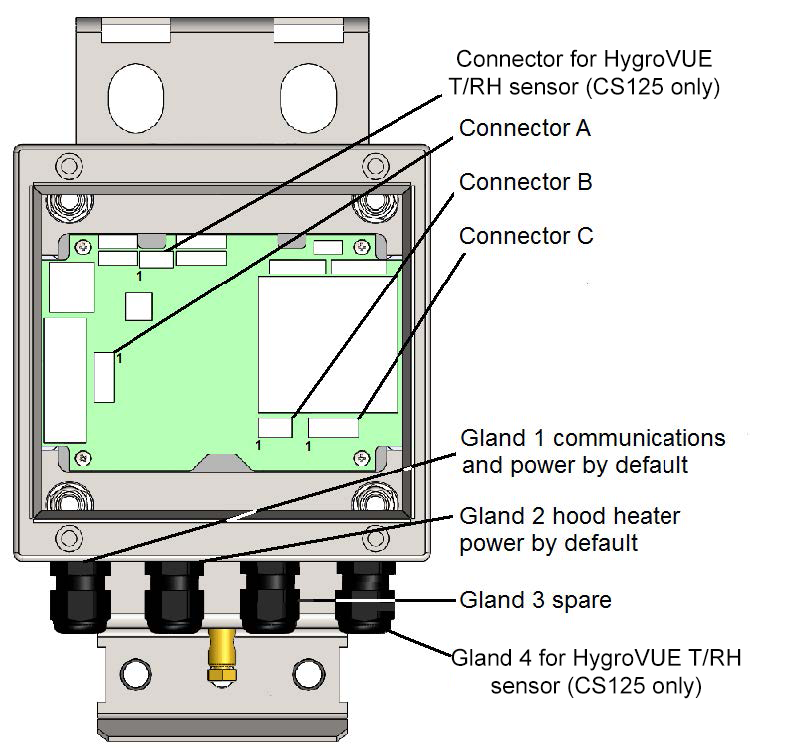
The sensor has four standard IP66 rated glands. By default, the first gland is used by the power/communications line, which includes the 7 to 30 V for the main electronics and the serial communications wires. The sensor is supplied with a 5 m cable already connected to the first gland.
The second gland is used for the 24 V feeds for the hood heaters and is fitted with a 5 m cable.
Glands 3 and 4 are spare. Optional user alarms usually use gland 3, and the optional HygroVue 5 or HygroVue 10 probe (CS125 only) usually uses gland 4.
To run cables through the cable glands, follow these guidelines. If a torque wrench is available, use a torque of 2.5 Nm to run cables through the cable glands. Otherwise, finger-tighten as tight as possible, then add a further ¾ turn with a 19 mm wrench/spanner.
Do not overtighten.
The glands are suitable for cables between 5 and 9 mm diameter.
If the power cable is incorrectly wired to the sensor, then damage can be done to the unit.
The longest recommended length for the supplied sensor cable is 10 m. Use a twisted-pair cable if the RS-485 cable needs to be longer than 10 m. Contact Campbell Scientific; if a cable longer than 10 m is needed.
Connections
|
Connector A – 5-pin connector |
||
|---|---|---|
|
Pin number |
Function |
Description |
| 1 | +V supply | Main electronics voltage supply input. |
| 2 | Ground | Auxiliary electronics ground; this connection is common with the main electronics ground. |
| 3 | Hood low (–V) or hood power ground |
If the hood heater supply is DC, connect the hood power low to this pin. If the hood heater supply is AC, connect the neutral or ground wire (if there is one) to this pin. |
| 4 | Ground | Auxiliary electronics ground; this connection is common with the main electronics ground. |
| 5 | Hood power high | If the hood heater supply is DC, connect the hood power high to this pin. If the hood heater supply is AC, connect the hood power voltage to this pin. |
Avoid damage to noise filters on the hood heater inputs.
-
If the heater voltage is DC, the hood power low should connect to pin 3 and the hood power high should connect to pin 5.
-
If the heater voltage is AC, connect the neutral wire (if there is one) to pin 3 and the hood power voltage to pin 5. Pin 3 should not be more than 5 V from the main electronics ground.
|
Connector B – 3-pin connector |
||
|---|---|---|
|
Pin number |
Function |
Description |
| 1 | G | Ground connection for serial communications; this connection is common with the main electronics ground (connector A, pin 2). |
| 2 | Receive | RS-232 receive line, RXD, B/D+ for RS-485 half duplex |
| 3 | Transmit | RS-232 transmit line, TXD, A/D− for RS-485 half duplex |
A 120 ohm termination resistor may be required to reduce signal distortion when using RS-485 for cable runs over about 500 m and baud rates above 38400. Connect the resistor between pins 2 and 3.
|
Connector C – 4-pin connector |
||
|---|---|---|
|
Pin |
Function |
Description |
| 1 | G | Ground connection for user alarms; this connection is common with the main electronics ground (connector A, pin 2). |
| 2 | User 2 | Output for user alarm 2. |
| 3 | G | Ground connection for user alarms; this connection is common with the main electronics ground (connector A, pin 2). |
| 4 | User 1 | Output for user alarm 1. |
|
Connector for HygroVue 5 or HygroVue 10 probe (CS125 only) |
|
|---|---|
|
Pin number |
Function |
| 1 | +12 V |
| 2 | SDI-12 input |
| 3 | G |
To use these connections, either use the cable gland connected to the hood heater power or, if the hood heater is also required, use different cables to those supplied. Contact Campbell Scientific for cable choice assistance.
