LoggerNet network map configuration
Once a serial or telemetry link between LoggerNet and the base station is physically established, LoggerNet needs to be configured to enable communications to occur through the base station and outward to the remote stations. The Setup Screen ![]() in LoggerNet is used to create a tree-list of stations and their connectivity settings, as well as details for related hardware. This list of devices shows in multiple locations throughout the software and is called the network map.
in LoggerNet is used to create a tree-list of stations and their connectivity settings, as well as details for related hardware. This list of devices shows in multiple locations throughout the software and is called the network map.
If Network Planner was used to configure your network of devices, you can use a function in that software to configure the network map of LoggerNet so it can communicate with the base station and the devices. Note the checkbox for configuring LoggerNet located in the Configure Devices checklist on the main screen. Once that task is executed, you will see the results of this configuration show up automatically in the Setup Screen of LoggerNet. This enables you to bypass the manual steps shown in this section. Refer to: s.campbellsci.com/documents/us/manuals/loggernet.pdf ![]() .
.
-
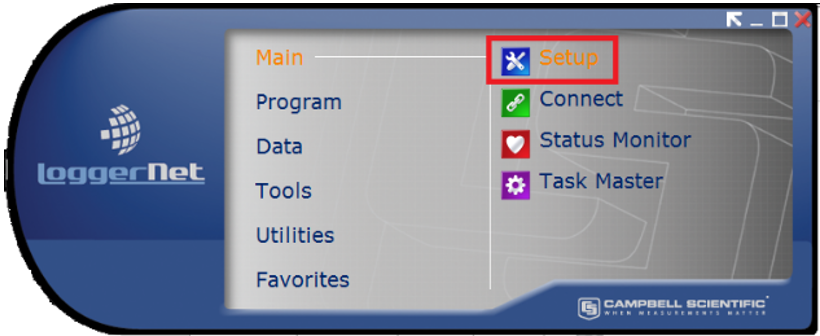
From the Main category of the LoggerNet toolbar, click Setup
 .
.
-
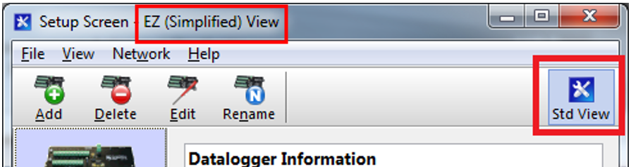
If the Setup Screen comes up in the EZSetup mode, click the Std View button to put it into the standard view mode.
-
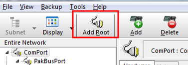
Click Add Root. When using a USB or serial cable connection to the base station, select ComPort for the type of root device. If you have a telemetry connection between LoggerNet and the base station, you will usually choose IPPort as the root device.
-
Select PakBusPort (PakBus Loggers).
-
Select CRVWSeries.
-
Click Close.
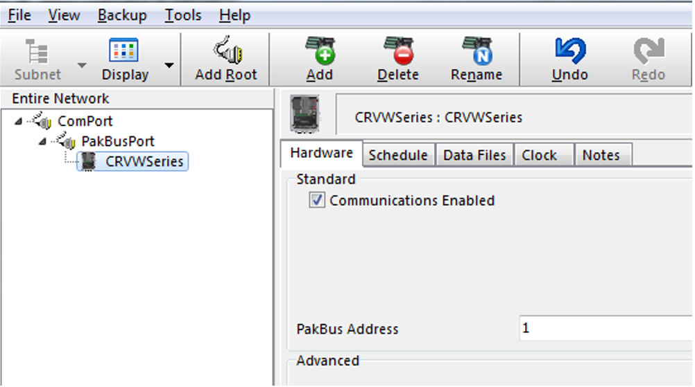
If you started with an empty network map, your Entire Network should look similar to the following image.
-
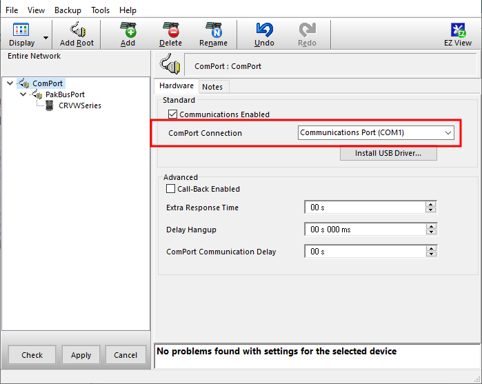
Click ComPort in the Entire Network pane.
-
On the Hardware tab, use the ComPort Connection drop-down selection box select the serial port to which the base radio is connected on your LoggerNet computer.
-
Click Apply to save your changes.
-
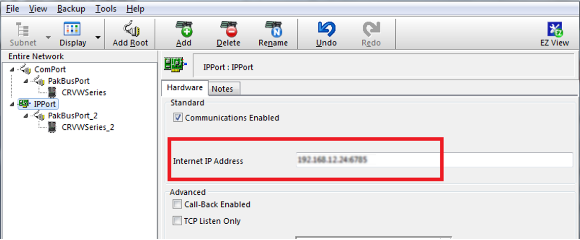
(IP option) Click IPPort device in the Entire Network pane.
-
On the Hardware tab, in the Internet IP Address box, enter the TCP/IP address and port number used to connect to your telemetry device at the base station location.
-
Click Apply.
-
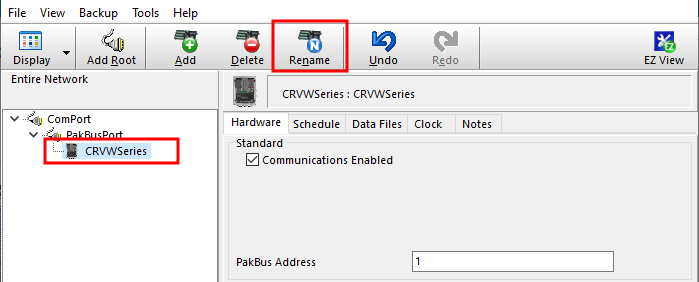
Click CRVWSeries in the network map. Click Rename and enter a device name.
-
On the Hardware tab, set the PakBus Address value to match the value that was configured into the device with Device Configuration Utility or with the Network Planner.
-
Click Apply.
NOTE:For more information about security codes, refer to your data logger manual or Device Configuration Utility help.
-
Select the Clock tab.
-
Click Check Clocks button to instruct LoggerNet to send a clock check command through the base station to the destination station. If the radio link is working, the current date and time should show up in the Adjusted Server Date/Time and Station Date/Time boxes within a few seconds.
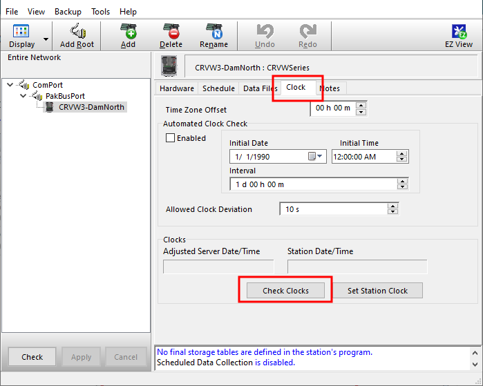
If LoggerNet returns an error after the clock check attempt, something is wrong with the radio link or the configuration of LoggerNet. Investigate at both the radio level and at the LoggerNet level. In-field validation with a temporary laptop computer running LoggerNet helps to validate radio links while still in the field and reduces the need to return to the sites to investigate radio problems.
If the clock check was successful, and you want the station time to be synchronized with the LoggerNet computer station time, click Set Station Clock.
-
Adding additional devices to your network map does not require re-entering ComPort, IPPort, or PakBusPort. Simply click on the existing PakBusPort device and click Add. Choose CRVWSeries from the list of data loggers and click Close. You will now have another device on the network map. It is recommended you rename devices as you add them to avoid any confusion.
-
Click on the new device and repeat the configuration process described earlier in this section. You will enter a unique PakBus Address for each device added. Repeat this process for every single-hop device in your network. Perform a clock check on each station as it is added. Click Apply in each case.
-
To add devices that are reached through a repeater station, click on the device that has been configured as a repeater station and click Add. Choose CRVWSeries from the data logger list and click Close. Now the device appears as a child device of the repeater. This will instruct LoggerNet to route through the repeater to communicate with the child device. Rename the device, configure it, and click Apply. Multiple child devices can be added to any repeater/parent. Using the tab screens, configure these devices in the same way as the other devices.