TCPsyc (Measure Peltier style thermocouple psychrometers)
The TCPsyc instruction is used to measure one or more Peltier (Spanner) style thermocouple psychrometers (TCP) attached either directly to a CR6 datalogger or via a relay multiplexer, such as the AM16/32B series, attached to a CR6 datalogger.
Syntax
TCPsyc ( Dest, Reps, DiffChan, TRef, OutputOption, IxCool, HeatTime, CoolTime, SampleOpt , MeasureTime )
This sample program measures one psychrometer wired to U1/U2. The instruction heats the psychrometer for 1 second, cools the psychrometer for 20 seconds, measures the depression voltage for 20 seconds then outputs the four parameters given by option 0. If option 1 is used, then the same 4 outputs are returned, plus all of the sampled uV measurements. The number of uV measurements is determined by the sample frequency (which is set by the sample option parameter) and the measure time parameter (allowable range is 5 to 60 secs).
'TCPsyc Example
'Declare Variables
Const REPS = 1
Const MeasFreq = 4 'Hz; set by sample option parameter
Const MeasTime =20 'Seconds
Public Meas(4*REPS+(MeasFreq * MeasTime))’use constants to scale array if using output option 1
Alias Meas(1) = Voffset
Alias Meas(2) = uVMax
Alias Meas(3) = Psi
Alias Meas(4) = Amb
Public Tref
BeginProg
Scan(1,min,0,0)
PanelTemp (Tref,60)
TCPsyc(Meas(),REPS,U1,Tref,0,-6000,1,20,2,20) 'sample option 2 = 4 Hz
NextScan
EndProg
Remarks
Up to six thermocouple psychrometers (TCP) can be measured when connected directly to a CR6 datalogger. Additional TCP sensors can be measured when attached to a relay multiplexer, such as the AM16/32B, connected to a CR6 datalogger.
Note: Wescor and JRD Merrill both make compatible psychrometers that share a similar design.
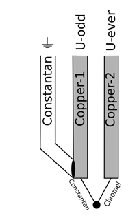
Wiring for the psychrometers is as follows:
| Wire Color | Wire | CR6 Channel | AM16/32B Mux | |
|---|---|---|---|---|
| Wescor | Red | Cu-2 | U Odd | H |
| Black | Cu-1 | U Even | L | |
| Blue/Bare | Const | Analog G | G | |
| JRD Merril | White | Cu-2 | U Odd | H |
| Blue | Cu-1 | U Even | L | |
| Red/Bare | Const | Analog G | G |
Parameters
Dest
A variable or variable array in which to store the results of the measurement. The variable must be dimensioned to accommodate all of the values returned by the instruction, which is determined by the Option parameter.
Type: Variable or Variable Array
RepsTCPsyc
The number of times the measurement should be made on consecutive U-channel pairs. If measurements are taken on a multiplexer, this parameter should be 1.
Type: Constant
DiffChan (Differential Channel)
Specifies the number of the universal terminal pair on which to make the first measurement. If the Reps parameter is greater than 1, additional measurements will be made on sequential channels.
| Code | Description |
|---|---|
| U1 | Universal Terminals 1 and 2 (U1 = high/U2 = low) |
| U3 | Universal Terminals 3 and 4 (U3 = high/U4 = low) |
| U5 | Universal Terminals 5 and 6 (U5 = high/U6 = low) |
| U7 | Universal Terminals 7 and 8 (U7 = high/U8 = low) |
| U9 | Universal Terminals 9 and 10 (U9 = high/U10 = low) |
| U11 | Universal Terminals 11 and 12 (U11 = high/U12 = low) |
Type: Constant
TRef (Temperature Reference)
The name of the variable that is the source of the reference temperature (or the result of the reference temperature measurement), in degrees C, for the thermocouple measurements. Right-click the parameter to display a list of defined variables.
Type: Variable, Array, or Expression
OutputOption
Determines the output of the instruction.
| Code | Description |
|---|---|
| 0 |
Outputs 4 values: Voltage Offset, Psychrometric depression in uVolts, Estimated Water Potential in MPa (Brown Model), and Sample Temperature in degrees C. Output array should be dimensioned to 4. |
| 1 | Output all 4 values from above followed by all of the sampled uVolt measurements. Output array should be dimensioned to the following: Array Size = 4 + (Sample Frequency x MeasTime). |
Type: Constant
IxCool
The IxCool A argument is the reverse biased current excitation used to cool the thermocouple junction via Peltier cooling. This argument is in µAmps and the allowable range is -4000 to -9000 µAmps.
Type: Constant
HeatTime
The time in seconds that a forward biased 10mA current will be applied to the thermocouple to heat and dry the junction prior to cooling. The allowable range is 0 – 5 seconds. A value of zero will skip heating and go directly to cooling the thermocouple junction.
Type: Constant
CoolTime
The time in seconds that the cooling current will be applied to the thermocouple psychrometer. The allowable range is 5 – 45 seconds.
Type: Constant
SampleOpt
Determines the frequency, in hertz (Hz), that the datalogger will measure the differential µV output caused by the temperature difference between the sensing thermocouple junction and the reference junction after the cooling excitation ends. This argument also determines the integration time on the individual differential voltage measurements (longer integration time increases the effective voltage resolution of each measurement yet decreases the potential temporal resolution options). See the Main help file for a list of sample options.
Type: Constant
MeasureTime
The total time in seconds that the µV output will be recorded for each psychrometer after excitation ends. The allowable range is 5 – 60 seconds.
Type: Constant