SPIOpen (Open SPI Communication)
The SPIOpen instruction sets up the datalogger to perform SPI communication as an SPI controller.
NOTE: Campbell Scientific documentation has been updated to replace legacy industry terms with modern terminology. Controller-peripheral are now used to describe SPI communications. The SPI controller initiates communications and makes requests of peripheral device(s). Peripheral devices process requests and return an appropriate response See https://www.oshwa.org/a-resolution-to-redefine-spi-signal-names for more information.
Syntax
SPIOpen ( BeginPort, BitRate, Option )
To demonstrate the operation of the SPI instructions to read an actual SPI device, the following describes reading an Analog Device ADXL350 3-axis accelerometer.
Since the device operates at 3.3V, all lines interfacing to the device must be set up accordingly. This device requires a Chip Select (CS) line to notify it of impending communication. Port C4 is used as the CS line.
'Declare Variables
Public Count as Long
Public id as long
Public D as Long
Public Dest(2) as Long
Public zero as Long
Dim pwr_ctrl as Long = {&H2D080000}
Dim bw_rate as Long = {&H2C060000}
Dim id_reg as Long = {&H80000000}
Dim Cfg as Long = {&H31000000}
Dim DReg as Long = {&HF2000000}
Public X as Long
Public Y as Long
Public Z as Long
BeginProg
PortPairConfig(C1,2) 'Configure C1/C2 as 3.3V
PortPairConfig(C3,2)'Configure C3/C4 as 3.3V
SPIOpen(C1,100000,&H60)'configure the SPI port for 100KHz operation with falling phase,
'low polarity, LSB first, 8 bit data.
PortSet(C4,0,1)'enable the CS
SPIWrite(C1,cfg,1)'write the data format register address
SPIWrite(C1,zero,1)'write the data format register with 0x0
PortSet(C4,1,1)
PortSet(C4,0,1)'enable the CS
SPIWrite(C1,id_reg,1)'write the id register address
SPIRead(C1,D,1)'read the id register
PortSet(C4,1,1)
movebytes(id,3,d,0,1)
PortSet(C4,0,1)'enable the CS
SPIWrite(C1,bw_rate,2)'Write the bwrate register with &H06
PortSet(C4,1,1)
PortSet(C4,0,1)'enable the CS
SPIWrite(C1,pwr_ctrl,2)'write the pwr_ctrl register with &H08
PortSet(C4,1,1)
Scan(1,sec,0,0)
Count += 1
PortSet(C4,0,1)
SPIWrite(C1,Dreg,1) 'send addr to read
SPIRead(C1,Dest,6) 'Read X, Y, and Z.
PortSet(C4,1,1)
movebytes(X,2,Dest,0,2) 'Move X into its own variable
movebytes(Y,2,Dest,2,2) 'Move Y into its own variable
movebytes(Z,2,Dest,4,2) 'Move Z into its own variable
NextScan
EndProg
Remarks
Note that a prior understanding of the operation and details of the SPI protocol is assumed.
SPIOpen must be declared prior to using SPIRead or SPIWrite.
Serial Peripheral Interface (SPI) protocol is a clocked synchronous interface that is used for short-distance communication, generally between embedded devices. When SPIOpen() is executed, three terminal blocks are dedicated to function as the SPI clock signal (SCK), Controller-Out, Peripheral-In signal (COPI), and Controller-In, Peripheral-Out signal (CIPO).
Parameters
BeginPort
The beginning port used for the three signals for SPI communications. The first port is the SPI clock signal. The next higher port from the clock port is the Controller Out Peripheral In (COPI) signal, and the next higher port is Controller In Peripheral Out (CIPO). BeginPort can be C1
Type: Constant
BitRate
The synchronous clock rate in hertz for the clock signal.
Type: Constant
Option
A bit field that is used to configure the operation of the SPI interface. The bits are defined as:
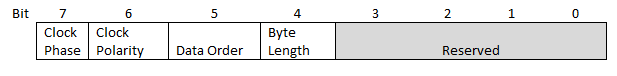
| Field | Description |
|---|---|
|
7 Clock Phase (CPHA) |
0 = Data is changed on the first CLK edge and captured on the following edge.
|
|
6 Clock Polarity (CPOL) |
0 = The inactive state is low; 1 = The inactive state is high. |
|
5 Data Order |
0 = LSB first; 1 = MSB first |
|
4 Byte length |
0 = 8 bit and 1 =7 bit |
For example: Option field of &H60 Phase=0, Polarity=1, Data=1 and Length=0
Or Option field of &H30 Phase=0, Polarity=0, Data=1 and Length=1
The Diagram below demonstrates different SPI interface configurations and may be used to match the configuration needed for your specific sensor:
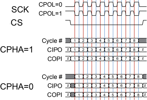
Source: https://commons.wikimedia.org/wiki/File:SPI_timing_diagram.svg
Type: Constant