SDMCan (SDM Can Interface)
The SDMCAN instruction is used to measure and control the SDM-CAN interface.
Syntax
SDMCAN ( Dest, SDMAddress, TimeQuanta, TSEG1, TSEG2, ID, DataType, StartBit, NumBits, NumVals, Multiplier, Offset )
The following example reads a 16-bit engine speed value from a CAN-bus network running at 250K baud.
'Set Scan Rate
Const Period=1
Const P_Units=2
' \ \ \ \ \ \ \ \ \ \ \ \ CANBUS Constants / / / / / / / / / / / /
'------------------------- Physical Network Parameters ------------
'Set SDM-CAN to 250K
Const TQUANT=4
Const TSEG1=5
Const TSEG2=2
'------------------------ Data Frame Parameters -------------------
'___________________ Canbus Block1_____________________
'Collect and retrieve 16-bit data value
'Data Type 1, unsigned integer, most significant byte first
Const CANREP1=1'Repetitions
Const ADDR1=0 'Address of SDM-CAN module
Const DTYPE1=1 'Data values to collect
Const STBIT1=33'Start position in data frame
Const NBITS1=16'Number of bits per value
Const NVALS1=1'Number of values
Const CMULT1=0.4'Multiplier
Const COSET1=0'Offset
Dim CANBlk1(CANREP1)'Dimensioned Dest
'\ \ \ \ \ \ \ \ \ \ \ \ Aliases and other Variables / / / / / / / /
Alias Canblk1(1)=Engine_Speed
'\ \ \ \ \ \ \ \ \ \ \ \ \ PROGRAM / / / / / / / / / / / / / / / / /
BeginProg
Scan (PERIOD,P_UNITS,0,0)
'____________________ CAN Blocks_______________________
'Retrieve Data from CAN-bus network
SDMCAN (CANBLK1(), ADDR1, TQUANT, TSEG1, TSEG2, 217056256, DTYPE1, STBIT1, NBITS1, NVALS1, CMULT1, COSET1)
NextScan
EndProg
Remarks
Multiple SDMCAN instructions may be used within a program. The initial function of the instruction is to configure the SDM-CAN interface when the datalogger program is compiled. Subsequent instructions can be used to determine what data is passed between the CAN-bus network and the datalogger, set and/or read the SDM-CAN's internal switches, and read and/or reset detected errors.
The parameter dialog box for the SDMCAN instruction has a Select .PCK Values button, which when selected allows the user to specify a PCK file from which to select the CAN-bus value to be returned. When a value is selected from the pick list the Destination, ID, DataType, StartBit, NumBits, Multiplier, and Offset parameters are populated from the data in the file. PCK files are generated by the DBC to SDMCan converter.
The SDMTrigger instruction can be used to trigger simultaneous measurements from one or more SDM-CANs and other SDM devices connected to the datalogger. When the SDMTrigger instruction is encountered in a program, it broadcasts a special SDM message which causes all the SDM-CAN devices to copy the last data values captured from the CAN-bus into the working data buffers. Refer to the SDM-CAN manual for additional help.
NOTE: If more than one CANBUS instruction is used within a datalogger program, the values used for TimeQuanta, TSEG1 and TSEG2 must be the same for each instruction.
Parameters
Dest
A variable array in which to store the results of the measurement. It must be an array of sufficient size to hold all of the values that will be returned by the function chosen (defined by the DataType parameter).
Type: Variable array
SDMAddress (Address of Device)
Defines the address of the device with which to communicate. Valid ![]() SDM Synchronous Device for Measurement. A processor-based peripheral device or sensor that communicates with the datalogger via hardwire over a short distance using a protocol proprietary to Campbell Scientific. addresses are 0 through 14. Address 15 is reserved for the SDMTrigger instruction.
SDM Synchronous Device for Measurement. A processor-based peripheral device or sensor that communicates with the datalogger via hardwire over a short distance using a protocol proprietary to Campbell Scientific. addresses are 0 through 14. Address 15 is reserved for the SDMTrigger instruction.
Some SDM instructions support repetitions. If a Reps parameter is present and it is greater than 1, the data logger will increment the SDM address used in the instruction for each subsequent device with which it communicates.
TimeQuanta
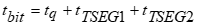
Three time segments are used to set the bit rate and other timing parameters for the CAN-bus network, TimeQuanta, TSEG1, and TSEG2. These parameters are entered as integer numbers. The relationship between the three time segments is defined as:
The first time segment, the synchronization segment (S-SG), is defined by the TimeQuanta parameter. To calculate a suitable value for TiimeQuanta, use the following equation:

where tq = the TimeQuanta. There are between 8 and 25 time quanta in the bit time. The bit time is defined as 1/baud rate.
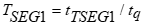
TSEG1
The second time segment, TSEG1, is actually two time segments known as the propagation segment and phase segment one. The value entered is determined by the characteristics of the network and the other devices on the network. It can be calculated as:
TSEG2
The third time segment, TSEG2 (the phase segment two), is defined by the TSEG2 parameter. The value of TSEG2 can be calculated using the equation:

The relative values of TSEG1 and TSEG2 determine when the SDM-CAN samples the data bit.
ID
Each device on a CAN-bus network prefaces its data frames with an 11 or 29 bit identifier. The ID parameter is used to set this address. The ID is entered as a single decimal equivalent. Enter a positive value to signify a 29 bit ID or a negative value to signify an 11 bit ID. Any value < -2047 will set the ID to an 11 bit ID of 0.
DataType
Defines what function the CANBUS instruction will perform. This instruction can be used to collect data, buffer data for transmission to the CAN-bus, transmit data to the CAN-bus, read or reset error counters, read the status of the SDM-CAN, read the SDM-CAN's OS signature and version, send a remote frame, or read or set the SDM-CAN's internal switches. Enter the numeric value for the desired option:
| Value | Description | |||||||||||||||||||||||||||||||||||||||||||||||||||||||||||||||
|---|---|---|---|---|---|---|---|---|---|---|---|---|---|---|---|---|---|---|---|---|---|---|---|---|---|---|---|---|---|---|---|---|---|---|---|---|---|---|---|---|---|---|---|---|---|---|---|---|---|---|---|---|---|---|---|---|---|---|---|---|---|---|---|---|
| 1 | Retrieve data; unsigned integer, most significant byte first | |||||||||||||||||||||||||||||||||||||||||||||||||||||||||||||||
| 2 | Retrieve data; unsigned integer, least significant byte first | |||||||||||||||||||||||||||||||||||||||||||||||||||||||||||||||
| 3 | Retrieve data; signed integer, most significant byte first | |||||||||||||||||||||||||||||||||||||||||||||||||||||||||||||||
| 4 | Retrieve data; signed integer, least significant byte first | |||||||||||||||||||||||||||||||||||||||||||||||||||||||||||||||
| 5 | Retrieve data; 4-byte IEEE floating point number; most significant byte first | |||||||||||||||||||||||||||||||||||||||||||||||||||||||||||||||
| 6 | Retrieve data; 4-byte IEEE floating point number; least significant byte first | |||||||||||||||||||||||||||||||||||||||||||||||||||||||||||||||
| 7 | Build data frame in SDM-CAN memory; unsigned integer, most significant byte first. Overwrite existing data | |||||||||||||||||||||||||||||||||||||||||||||||||||||||||||||||
| 8 | Build data frame in SDM-CAN memory; unsigned integer, least significant byte first. Overwrite existing data. | |||||||||||||||||||||||||||||||||||||||||||||||||||||||||||||||
| 9 | Build data frame in SDM-CAN memory; signed integer, most significant byte first. Overwrite existing data. | |||||||||||||||||||||||||||||||||||||||||||||||||||||||||||||||
| 10 | Build data frame in SDM-CAN memory; signed integer, least significant byte first. Overwrite existing data. | |||||||||||||||||||||||||||||||||||||||||||||||||||||||||||||||
| 11 | Build data frame in SDM-CAN memory; 4-byte IEEE floating point number; most significant byte first. Overwrite existing data. | |||||||||||||||||||||||||||||||||||||||||||||||||||||||||||||||
| 12 | Build data frame in SDM-CAN memory; 4-byte IEEE floating point number; least significant byte first. Overwrite existing data. | |||||||||||||||||||||||||||||||||||||||||||||||||||||||||||||||
| 13 | Build data frame in SDM-CAN memory; unsigned integer, most significant byte first. Logical "OR" with existing data. | |||||||||||||||||||||||||||||||||||||||||||||||||||||||||||||||
| 14 | Build data frame in SDM-CAN memory; unsigned integer, least significant byte first. Logical "OR" with existing data. | |||||||||||||||||||||||||||||||||||||||||||||||||||||||||||||||
| 15 | Build data frame in SDM-CAN memory; signed integer, most significant byte first. Logical "OR" with existing data. | |||||||||||||||||||||||||||||||||||||||||||||||||||||||||||||||
| 16 | Build data frame in SDM-CAN memory; signed integer, least significant byte first. Logical "OR" with existing data. | |||||||||||||||||||||||||||||||||||||||||||||||||||||||||||||||
| 17 | Build data frame in SDM-CAN memory; 4-byte IEEE floating point number; most significant byte first. Logical "OR" with existing data. | |||||||||||||||||||||||||||||||||||||||||||||||||||||||||||||||
| 18 | Build data frame in SDM-CAN memory; 4-byte IEEE floating point number; least significant byte first. Logical "OR" with existing data. | |||||||||||||||||||||||||||||||||||||||||||||||||||||||||||||||
| 19 | Transmit data value to the CAN-bus; unsigned integer, most significant byte first. | |||||||||||||||||||||||||||||||||||||||||||||||||||||||||||||||
| 20 | Transmit data value to the CAN-bus; unsigned integer, least significant byte first. | |||||||||||||||||||||||||||||||||||||||||||||||||||||||||||||||
| 21 | Transmit data value to the CAN-bus; signed integer, most significant byte first. | |||||||||||||||||||||||||||||||||||||||||||||||||||||||||||||||
| 22 | Transmit data value to the CAN-bus; signed integer, least significant byte first. | |||||||||||||||||||||||||||||||||||||||||||||||||||||||||||||||
| 23 | Transmit data value to the CAN-bus; 4-byte IEEE floating point number; most significant byte first. | |||||||||||||||||||||||||||||||||||||||||||||||||||||||||||||||
| 24 | Transmit data value to the CAN-bus; 4-byte IEEE floating point number; least significant byte first. | |||||||||||||||||||||||||||||||||||||||||||||||||||||||||||||||
| 25 | Transmit previously built data frame to the CAN-bus. | |||||||||||||||||||||||||||||||||||||||||||||||||||||||||||||||
| 26 | Set up previously built data frame as a Remote Frame Response. | |||||||||||||||||||||||||||||||||||||||||||||||||||||||||||||||
| 27 | Read Transmit, Receive, Overrun, and Watchdog errors. The errors are placed consecutively in the array specified by the Dest parameter. | |||||||||||||||||||||||||||||||||||||||||||||||||||||||||||||||
| 28 | Read Transmit, Receive, Overrun, and Watchdog errors. The errors are placed consecutively in the array specified by the Dest parameter. Reset error counters to 0 after reading. | |||||||||||||||||||||||||||||||||||||||||||||||||||||||||||||||
| 29 |
Read SDM-CAN status; result is placed into the array specified in the Dest parameter. The result codes are as follows:
|
|||||||||||||||||||||||||||||||||||||||||||||||||||||||||||||||
| 30 | Read SDM-CAN operating system and version number; results are placed in two consecutive array variables beginning with the variable specified in the Dest parameter. | |||||||||||||||||||||||||||||||||||||||||||||||||||||||||||||||
| 31 | Send Remote Frame Request. | |||||||||||||||||||||||||||||||||||||||||||||||||||||||||||||||
| 32 |
Set SDM-CAN's internal switches. The code is stored in the array specified in the Dest parameter and is entered in the form of ABCD.
|
|||||||||||||||||||||||||||||||||||||||||||||||||||||||||||||||
| 33 | Read SDM-CAN's internal switches. Place results in the array specified in the Dest parameter. |
StartBit
Used to identify the least significant bit of the data value within the CAN data frame to which the instruction relates. The bit number can range from 1 to 64 (there are 64 bits in a CAN data frame). The SDM-CAN adheres to the ISO standard where the least significant bit is referenced to the right most bit of the data frame. If a negative value is entered, the least significant bit is referenced to the left most bit of the data frame.
NumBits
The NumBits parameter is used to specify the number of bits that will be used in a transaction. The number can range from 1 to 64 (there are 64 bits in a CAN data frame).
The SDM-CAN can be configured to notify the datalogger when new data is available by setting a control port high. This allows data to be stored in the datalogger tables faster than the program execution interval. This interrupt function is enabled by entering a negative value for this parameter.
NOTE: This parameter may be overridden by a fixed number of bits, depending upon the data type selected.
NumVals
The NumVals parameter defines the number of values (beginning with the value stored in the Dest array) that will be transferred to or from the datalogger during one operation. For each value transferred, the Number of Bits (NumBits) will be added to the Start Bit number so that multiple values can be read from or stored to one data frame.
Mult, Offset (Multiplier and Offset)
Factors by which to scale the raw results of the measurement. Typically used to convert the raw measurement to engineering units or to units other than which is output. For example, the TCDiff instruction measures a thermocouple and outputs temperature in degrees C. A multiplier of 1.8 and an offset of 32 will convert the temperature to degrees F.
For temperature measurements, a multiplier (mult) of 1 and an offset of 0, would output in degrees Celsius. For analog measurements, a multiplier (mult) of 1 and an offset of 0, would output the measured voltage in millivolts divided by the excitation voltage in volts.
If Repetitions of greater than 1 are used for this instruction, Repetitions can also be used for the Multiplier and Offset. See Multipliers, Offsets, and Disable Variables with Repetitions for more information.
Type: Constant, Variable, Array, or Expression