I2COpen (Set up I2C)
The I2COpen instruction sets up the datalogger for Inter-Integrated Circuit (I2C) communications.
NOTE: Campbell Scientific documentation has been updated to replace legacy industry terms with modern terminology. Controller-peripheral are now used to describe I2C communications. The I2C controller initiates communications and makes requests of peripheral device(s). Peripheral devices process requests and return an appropriate response.
Syntax
I2COpen ( BeginPort, BitRate )
Example 1
The following program configures and reads accelerometer data from an ADLX350 3-axis accelerometer. It is a 3.3V device so C1 and C2 and set up to operate at 3.3V.
The program reads the ID from the device. This requires writing the address to read then reading the data. Example:
Dim id_reg as Long = {&H80000000} 'This defines the value to send to access the ID register in the ADXL350
I2CWrite(C1,&H53,id_reg,1,&H2) 'Start with no stop, Send &H80 to the device, leave the bus active
I2CRead(C1,&H53,tmp,2,&H5) 'restart with stop, read the id register
movebytes(id,3,tmp,0,1) 'store the value read
In order to read accelerometer data, the ADXL350 must be configured. This is done by writing the BWrate register and the pwr_ctrl register. Refer to the ADXL350 for details on the register definitions.
The following lines of CRBASIC configure the ADXL350:
Dim pwr_ctrl as Long = {&H2D080000} 'Register &H2D is to be written with Data &H08
Dim bw_rate as Long = {&H2C060000} 'Register &H2C is to be written with Data &H06
I2CWrite(C1,&H53,bw_rate,2,&H3) 'Start and Stop, configure the bwrate register
I2CWrite(C1,&H53,pwr_ctrl,2,&H3) 'Start and Stop, enable measurements
Public Count as Long
Public id as long
Public tmp as Long
Public Dest(2) as Long
Public zero as Long
Dim pwr_ctrl as Long = {&H2D080000}
Dim bw_rate as Long = {&H2C060000}
Dim id_reg as Long = {&H80000000}
Dim Cfg as Long = {&H31000000}
Dim DReg as Long = {&HF2000000}
Public X as Long
Public Y as Long
Public Z as Long
BeginProg
PortPairConfig(C1,2) 'Set up C1,C2 as 3.3V
PortPairConfig(C3,2) 'Set up C3,C4 as 3.3V (for CS signal)
PortSet(C4,1,1) 'Drive the CS signal
I2COpen(C1,1000)
I2CWrite(C1,&H53,id_reg,1,&H2) 'Start with no stop
I2CRead(C1,&H53,tmp,2,&H5) 'restart with stop, read the id register
movebytes(id,3,tmp,0,1)
I2CWrite(C1,&H53,bw_rate,2,&H3) 'configure the bwrate register
I2CWrite(C1,&H53,pwr_ctrl,2,&H3) 'enable measurements
Scan(1,sec,0,0)
Count += 1
I2CWrite(C1,&H53,Dreg,1,&H2) 'send addr to read
I2CRead(C1,&H53,Dest,6,&H5) 'Read X,Y, and Z
movebytes(X,2,Dest,0,2)
movebytes(Y,2,Dest,2,2)
movebytes(Z,2,Dest,4,2)
NextScan
EndProg
Example 2
This program demonstrates using a SHT31 sensor with I2C output to retrieve temperature and humidity data.
'Wiring
'VDD - 5 volt
'C1 - Clock SCL
'C2 - Data SDA
'G - Ground
ConstTable Station_Constants
Const ScanInterval = 10 'Scan Interval
Const ScanUnit = Sec 'Scan Unit
Const TFInterval = 60 'Table File Interval
Const TFUnit = min 'Table File Unit
Const I2C_Sensors = True 'Use I2C Sensors
Const I2C_port = C1 'C1 -> SCL, C2 -> SDA
Const I2C_BaudRate =5000
Const I2C_volt = 1 '1 -> 5V, 2 -> 3V3
Const I2C_Delay = 20 'mSec
Const SHT3X = True 'SHT3X I2C Temperature and Humidity Sensor
Const SHT_adress = &H44
Const HeatDelay As Long = 0 'mSec the heater will be on before measurement
EndConstTable
Public PTemp, Batt_volt
Public ReadSHT_OK As Boolean
Function ReadSHT () As Boolean
Const DReg As Long = &H24000000 'Measurement command for single shot data acquisition
Const StatReg As Long = &HF32D0000 'Get status register
Const HeatOn As Long = &H306D0000 'Turn heater on
Const HeatOff As Long = &H30660000 'Turn heater on
Dim statusOn As Long
Dim statusOff As Long
Dim dest(2) As Long' is able to read up to 8 bytes
Dim ta0 As Long ' raw data
Dim rh0 As Long
Public SHT_Temp As Float : Units SHT_Temp = °C 'Final temperature
Public SHT_RH As Float : Units SHT_RH = % 'Final relative humidity
'Set up for I2C
I2COpen(I2C_port,I2C_BaudRate)
Delay(0,I2C_Delay,mSec)
'Read Temperature (before turning on the heater to avoid internal heating, can be 0.35-0.5 °C)
I2CWrite (I2C_port, SHT_adress, DReg, 2,&H03)
Delay (1,20,mSec)'Needed
I2CRead (I2C_port, SHT_adress, dest, 6, &H03)
MoveBytes(ta0, 2, dest ,0, 2)
SHT_Temp = -45 + 175 * ta0 / 65535
'Turn heater on
I2CWrite (I2C_port, SHT_adress, HeatOn, 2,&H03)
I2CWrite (I2C_port, SHT_adress,StatReg, 2,&H03)
I2CRead (I2C_port, SHT_adress, statusOn, 2, &H03)
statusOn = (statusOn >> (16+13)) AND &H00000001 'Heater status is in bit 13
Delay (1,HeatDelay,mSec) 'Time to keep heater on before measurement
'Read Humidity
I2CWrite (I2C_port, SHT_adress, DReg, 2,&H03)
Delay (1,20,mSec)'Needed
I2CRead (I2C_port, SHT_adress, dest, 6, &H03)
MoveBytes(rh0, 2, dest, 3, 2)
SHT_RH = 100 * rh0 / 65535
'Turn heater off
I2CWrite (I2C_port, SHT_adress, HeatOff, 2,&H03)
I2CWrite (I2C_port, SHT_adress,StatReg, 2,&H03)
I2CRead (I2C_port, SHT_adress, statusOff, 2, &H03)
statusOff = (statusOff >> (16+13)) AND &H00000001 'Heater status is in bit 13
If (SHT_Temp <> 130 OR SHT_RH <> 100) AND statusOn = 1 AND statusOff = 0
Return True
Else
Return False
EndIf
EndFunction
'Declare Private Variables
'Example:
'Dim Counter
'Define Data Tables
DataTable (Test,1,-1) 'Set table size to # of records, or -1 to auto allocate.
DataInterval (0,60,Sec,10)
Minimum (1,Batt_volt,FP2,False,False)
Sample (1,PTemp,FP2)
EndTable
'Main Program
BeginProg
PortPairConfig(I2C_port,I2C_volt)
I2COpen(I2C_port,I2C_BaudRate)
Scan (ScanInterval,ScanUnit,0,0)
PanelTemp (PTemp,50)
Battery (Batt_volt)
ReadSHT_OK = ReadSHT() 'Read SHT3X Temperature and Humidity
SW12 (SW12_1,0)
'Enter other measurement instructions
'Call Output Tables
'Example:
CallTable Test
NextScan
EndProg
Remarks
I2C uses two bidirectional open-drain lines, the Serial Data Line (SDA) and Serial Clock Line (SCL) pulled up with resistors. By definition, I2C is a Multi-Controller, Multi-Peripheral communication interface; however the datalogger only supports Single-Controller, Muti-Peripheral configurations. The datalogger provides pull-ups to allow communications, but the pull resistors are not strong enough for high speed communications. If higher speeds are required, external pull-up resistors will be necessary. The datalogger does not support “clock stretching”, where the peripheral can slow down the clock by holding the SCL line low. However, the BitRate parameter can be used to slow or speed up the clock.
NOTE: A prior understanding of the operation and details of the I2C protocol is assumed.
I2COpen must be declared prior to using I2CRead or I2CWrite.
Parameters
BeginPort (Begin Port)
Specifies the beginning port used for the two signals for I2C communications. The first port is the clock signal and the next higher port is used for the data signal. Valid options are C1, C3,
Type: Constant
BitRate (Bit Rate)
The bit rate, in Hertz, to use for communications.
Type: Constant
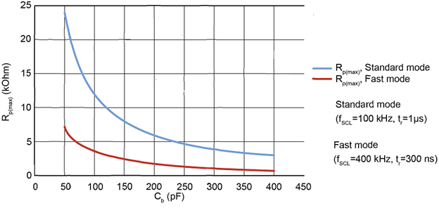
NOTE: The datalogger's 100k ohm pull-up resistors are too weak for communication at the standard clock frequency of 100kHz. Therefore, to run at faster speeds, an external pull-up resistor should be added. The external resistor can either be pulled to the +5V supply on the terminal blocks or it can be pulled high by another control port that is not being used for the I2C function. The control port (Cx) can be configured to drive at either +5V or +3.3V with the PortPairConfig() instruction. The external pull-up resistor should be sized appropriately for the speed and capacitance of the cable. Refer to the following graph to determine the appropriate external pullup resistor size.