Estimation of Dew Point
Dew point can be measured directly, to a high degree of accuracy, using traditional devices such as cooled mirror hygrometers, etc. However, such devices are often very expensive, require regular maintenance and may need air pumps. They are also heavy on power consumption.
An alternative method uses relatively inexpensive RH and Temperature sensors, in conjunction with a Campbell Scientific datalogger, to calculate dew point. While end results may not be quite as accurate as traditional dedicated devices, they are acceptable for a wide range of applications.
Calculating Dew Point
Dew point temperature can be calculated by Campbell Scientific dataloggers with the DewPoint instruction (see DewPoint (Dew Point) for more information).
The dew point temperature is found from the vapor pressure, relative humidity, and the saturation vapor pressure. The saturation vapor pressure is found from the dry bulb temperature, and the vapor pressure from saturation vapor pressure and relative humidity.
The dew point is found from Tetens' equation solved for dew point with coefficients optimized for the temperature range of -35 to +50 degrees C.
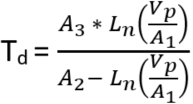
where:
Td = dew point temperature
A1 = 0.61078
A2 = 17.558
A3 = 241.88
The result is in degrees C. Error rate with this formula is less than 0.1 degrees C.
Error in the Estimation of Dew Point
Teten’s equation is an approximation of the true variation of saturated vapour pressure as a function of temperature. However, the errors in using the inverted form of the equation result in dew point errors much less than 0.1°C.
The largest component of error, in reality, comes from errors in the absolute calibration of the temperature and RH sensor.
Figure 1 shows how dew point varies as a function of temperature and humidity. It can be seen that the response is non-linear with respect to both variables. Errors in the measurement of RH and temperature thus form a complex function in relation to the resultant error in estimated dew point. In practice, the effect of errors in the calibration of air temperature can be taken to translate to an equivalent error in dew point, for example if the air temperature sensor is 0.2°C high, then the estimated dew point is approximately 0.2°C high. Figure 2 shows the errors in dew point as a function of a ‘worst case’ 5% error in the calibration of the RH sensor.
For sensors installed in the field there are additional errors associated with exposure of the sensor, for example sensors in unaspirated shields get slightly warmer than true air temperature in conditions of low wind speeds and high solar radiation. However, if the RH and air temperature sensors are installed in the same shield and are thus exposed identically, the estimate of dew point is not subject to the same error as the measurement of air temperature would be. This is because the temperature sensor will measure the actual temperature of the RH sensor, which is what is required for the derivation of air vapor pressure and thereby dew point.

Figure 1. Dew Point Temperature over the RH Range for Selected Air Temperatures
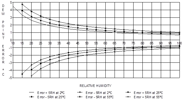
Figure 2. Effect of RH Errors on Calculated Dew Point (>±5 RH Unit Error at Three Air Temperature)