CurrentSE (Single-Ended Current)
The CurrentSE instruction is used to make a single-ended
current measurement on
NOTE: COMPATIBLE ONLY WITH CR6 SERIAL NUMBERS ≥ 7502 CONTAINING BOARD REVISION 19 OR LATER
Syntax
CurrentSE ( Dest, Reps, Range, RGChan, MeasOff, SettlingTime, fN1, Mult, Offset)
Following is a program showing the use of the CurrentSE instruction.
'Declare
Variables
Public Cur_SE
DataTable(Hourly,True,-1)
DataInterval(0,60,Min,0)
Sample(1,Cur_SE,IEEE4)
Average(1,Cur_SE,IEEE4,0)
Minimum(1,Cur_SE,IEEE4,0,0)
Maximum(1,Cur_SE,IEEE4,0,0)
EndTable
BeginProg
Scan(1,Sec,1,0)
'Generic CurrentSE measurement:
CurrentSE(Cur_SE,1,
CallTable(Hourly)
NextScan
EndProg
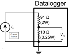
Remarks
The datalogger has built-in
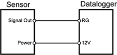
The following image shows the typical wiring for a 2-wire transmitter using datalogger power.
Parameters
Dest (Destination)
The Variable in which to store the results of the instruction. Right-click the parameter to display a list of defined variables.
If this instruction has a Repetitions parameter and it is greater than 1, the results are stored in an array with the variable name. The array must be dimensioned large enough to hold all of the values returned from all of the Reps.
Type: Variable or Array
Reps (Repetitions)
The number of repetitions for the measurement or instruction.
Type: Constant integer (or expression that evaluates as a constant).
For the CurrentSE instruction, measurements are made on consecutive channels. If the Reps parameter is greater than 1, the Dest parameter must be a variable array.
Range
The expected input from the sensor. To choose the appropriate range, multiply the expected current by 10 (ohms).
Right-click the parameter to display a list or enter the code directly.
| Code | Description |
|---|---|
| mV1000 | +1000 mV |
| mv200 | +200 mV |
| Autorange | Datalogger tests for and uses most suitable range |
For signals that do not fluctuate too rapidly, AutoRange allows the datalogger to automatically choose the input voltage range. AutoRange results in two voltage measurements being performed. The first voltage measurement is done quickly at a first notch frequency (fN1) of 50 kHz, the result of which determines the input voltage range to use for the second measurement. Autorange should not be used if fast measurements are required or if the analog signal could change significantly over the course of the measurement.
Type: Constant
RGChan (Resistive Ground Channel)
The CR6 has only one RG terminal.
Type: Constant
MeasOff (Measure Offset Voltage)
Determines whether the ground offset voltage is measured before the measurement is made on the analog channel. If the ground offset is measured it is subtracted from the sensor measurement and the result is stored in Dest.
| Value | Result |
|---|---|
| 0 | Offset voltage is corrected from background calibration. |
| 1 | Offset voltage is measured each scan (this option effectively increases the measurement time as if an additional rep were added to the instruction). |
Type: Constant
Settling Time
The settling time is the duration (in microseconds) to allow for signal settling after setting up a measurement (switching to the channel, setting the excitation) and before making the measurement.
Additional settling time may be necessary to allow the signal to settle with high resistance or long lead lengths (higher capacitance). The time it will take to make the measurement will include the measurement itself, the SettlingTime, fN1, and whether or not parameters are set to remove voltage offset errors. Using either RevDiff or RevEx causes two SettlingTimes to occur per channel; four SettlingTimes will occur when using both RevDiff and RevEx.
Type: Constant (or expression that evaluates as a constant)
fN1
Determines the lowest frequency that will be eliminated or notched out by the sinc filter. This filter notches out frequencies at integer multiples of fN1 by averaging for a time equal to 1/fN1;
thus, lower fN1 frequencies result in longer measurement times.
| Option | Description |
|---|---|
| 15000 | Performs a 0.0667 millisecond integration (for fast measurements) |
| 60 (or _60Hz) | Performs a 16.67 millisecond integration (filters 60 Hz noise) |
| 50 (or _50Hz) | Performs a 20 millisecond integration (filters 50 Hz noise) |
Type: Constant
Mult, Offset (Multiplier and Offset)
Factors by which to scale the raw results of the measurement. Typically used to convert the raw measurement to engineering units or to units other than which is output. For example, the TCDiff instruction measures a thermocouple and outputs temperature in degrees C. A multiplier of 1.8 and an offset of 32 will convert the temperature to degrees F.
For temperature measurements, a multiplier (mult) of 1 and an offset of 0, would output in degrees Celsius. For analog measurements, a multiplier (mult) of 1 and an offset of 0, would output the measured voltage in millivolts divided by the excitation voltage in volts.
If Repetitions of greater than 1 are used for this instruction, Repetitions can also be used for the Multiplier and Offset. See Multipliers, Offsets, and Disable Variables with Repetitions for more information.
Type: Constant, Variable, Array, or Expression
Related Sensors
This instruction is used by the following sensors:
- 4-20 mA Current Transmitter
- CURS100
NOTE: This is not an all-inclusive list of sensors that require this instruction. Refer to the owners manual of your device for more specific instructions.