BrHalf (Half Bridge Measurement)
The BrHalf instruction is used to make a half bridge measurement.
Syntax
BrHalf ( Dest, Reps, Range, SEChan, ExChan, MeasPEx, ExmV, RevEx, SettlingTime, fN1, Mult, Offset )
This program provides an example use of the BRHalf instruction. It is used to measure an RM Young Wind Monitor.
'Example program to measure the 05103
RM Young Wind Monitor using the
'BrHalf measurement
instruction.
'Declare Variables and
Units
Public WS_ms
Public WindDir
Units WS_ms=meters/second
Units WindDir=Degrees
'Define Data Tables
DataTable(Table1,True,-1)
DataInterval(0,60,Min,0)
WindVector
(1,WS_ms,WindDir,IEEE4,0,0,0,0)
FieldNames("WS_ms_S_WVT,WindDir_D1_WVT,WindDir_SD1_WVT")
EndTable
'Main Program
BeginProg
Scan(5,Sec,1,0)
'05103
Wind Speed & Direction Sensor measurements WS_ms and WindDir:
PulseCount(WS_ms,1,U11,1,1,0.098,0)
BrHalf(WindDir,1,mv5000C,U1,U5,1,2500,True,0,15000,355,0)
'Call
Data Tables and Store Data
CallTable(Table1)
NextScan
EndProg
Remarks
This instruction applies an excitation voltage, delays a specified amount of time, and then makes a single ended voltage measurement. With a multiplier of 1 and an offset of 0 the result is the ratio of the measured voltage divided by the excitation voltage.
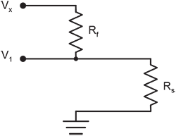
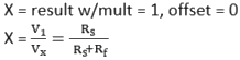
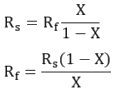
Relational Formula:
NOTE: Terminal assignments for this instruction must fall within the guidelines for universal terminal pairs.
Parameters
Dest (Destination)
The Variable in which to store the results of the instruction. Right-click the parameter to display a list of defined variables.
If this instruction has a Repetitions parameter and it is greater than 1, the results are stored in an array with the variable name. The array must be dimensioned large enough to hold all of the values returned from all of the Reps.
Type: Variable or Array
For the BrHalf instruction, the Dest parameter is a variable in which to store the results (X in the equation) of the measurement.
Reps (Repetitions)
The number of repetitions for the measurement or instruction.
Type: Constant integer (or expression that evaluates as a constant).
For the BrHalf instruction, the Reps parameter is the number of times the measurement should be made. Measurements are made on consecutive channels. If the Reps parameter is greater than 1, the Dest parameter must be a variable array.
Range
The voltage range for the measurement. An alphanumeric code is entered. Right-click the parameter to display a list or enter the code directly.
| Code | Description |
|---|---|
| mV5000 | +5000 mV |
| mV1000 | +1000 mV |
| mv200 | +200 mV |
| Autorange | Datalogger tests for and uses most suitable range. |
| AutorangeC | Autorange, checks for open input. |
| mV5000C | +5000 mV, checks for open input, sets excitation to ~ |
| mV1000C | +1000 mV, checks for open input, sets excitation to ~1250 mV. |
| mV200C | +200 mV, checks for open input, sets excitation to ~1250 mV. |
For signals that do not fluctuate too rapidly, AutoRange allows the datalogger to automatically choose the input voltage range. AutoRange results in two voltage measurements being performed. The first voltage measurement is done quickly at a first notch frequency (fN1) of 50 kHz, the result of which determines the input voltage range to use for the second measurement. The second measurement is then performed using the range determined from the first measurement, along with the fN1 chosen for the measurement instruction. Both measurements use the settling time chosen for the particular measurement instruction. Auto-ranging optimizes resolution but takes longer than a fixed range measurement because of the two-measurement sequence. The exception to this two-measurement sequence is if Reps are made on the same channel (Reps parameter is negative). In this instance, the test measurement is made only once. Subsequent repetitions are made with the delay between each measurement being the specified settling time. Autorange should not be used if fast measurements are required or if the analog signal could change significantly over the course of the measurement.
The C options check for an open connection on the analog input by applying a short overranging test signal to the analog input prior to making the measurement. For a voltage range of mv5000C,
The open-detect option may not work properly in the presence of external leakage (< 1 MOhm) to ground, as the overrange test signal could discharge through the external leakage during the input settling time such that an overrange condition no longer exists. In this case the measurement settling time should be minimized to minimize the discharge time of the overrange test signal.
The open circuit detection (C option) can cause measurement errors for slow responding sensors, as such sensors may not have sufficient time to recover from the applied short duration (50 microseconds) test signal. For such sensors, increasing the measurement settling time beyond the default may be necessary for sufficient sensor recovery time. If measurement speed is critical with a slow responding sensor, then it may be preferable to not use the open detect (C option).
Type: Constant
SEChan
The single-ended channel number on which to make the first measurement. When Reps are used, subsequent measurements will be automatically made on the following channels.
Type: Constant
For the BRHalf instruction, if the SEChan number is entered as a negative value, all Reps are performed
on the same channel (burst measurement). The burst measurement sampling rate is determined by the fN1 (first notch frequency) parameter![]() ADC Analog to digital conversion. The process that translates analog voltage levels to digital values. flush time (which is 810µS). The sample interval resolution is 1/93750Hz. The specified notch frequency will use the nearest multiple of (1/93750Hz) to get as close to the specified frequency as possible
ADC Analog to digital conversion. The process that translates analog voltage levels to digital values. flush time (which is 810µS). The sample interval resolution is 1/93750Hz. The specified notch frequency will use the nearest multiple of (1/93750Hz) to get as close to the specified frequency as possible
ExChan (Excitation Channel)
Specifies the
An alphanumeric code is entered. Right-click within the parameter to display a list.
| Code | Description |
|---|---|
| U1 | Universal Terminal 1 |
| U2 | Universal Terminal 2 |
| U3 | Universal Terminal 3 |
| U4 | Universal Terminal 4 |
| U5 | Universal Terminal 5 |
| U6 | Universal Terminal 6 |
| U7 | Universal Terminal 7 |
| U8 | Universal Terminal 8 |
| U9 | Universal Terminal 9 |
| U10 | Universal Terminal 10 |
| U11 | Universal Terminal 11 |
| U12 | Universal Terminal 12 |
Type: Constant
MeasPEx (Excitation Channels)
The number of sensors to excite with the same excitation terminal before automatically advancing to the next excitation terminal. To excite all sensors with the same excitation terminal, the value of this parameter should be set equal to the value of the Reps parameter.
This parameter in a bridge measurement can be used when the sensors to be measured outnumber the available excitation channels. It allows multiple sensors to be excited with each excitation channel.
For example, assume it is desired to measure eight pressure transducers that have 350 ohm full bridge strain gages to be excited by 5 volts. Each transducer requires 14 mA (5 volts/350 ohms = 14 mA). Since each excitation channel can provide a maximum of 50 mA at 5 volts, a maximum of 3 pressure transducers can be excited per channel (50 mA/14 mA = 3.57). To measure the eight transducers, 8 would be entered for the Reps argument and 3 for the MeasPEx. The first three transducers would all be connected to the first excitation channel, the next 3 to the second excitation channel, and the last 2 to the third excitation channel.
Type: Constant (or expression that evaluates as a constant)
ExmV (Excitation Voltage in mV)
The excitation, in millivolts, to apply to the excitation channel. The allowable range is
Type: Constant. For ExciteV() only, this parameter can also be a Variable.
For the BrHalf instruction, the ExmV argument is the excitation, in millivolts, to apply to the sensor.
RevEx (Reverse Excitation)
Type: Constant
Settling Time
The settling time is the duration (in microseconds) to allow for signal settling after setting up a measurement (switching to the channel, setting the excitation) and before making the measurement.
Additional settling time may be necessary to allow the signal to settle with high resistance or long lead lengths (higher capacitance). The time it will take to make the measurement will include the measurement itself, the SettlingTime, fN1, and whether or not parameters are set to remove voltage offset errors. Using either RevDiff or RevEx causes two SettlingTimes to occur per channel; four SettlingTimes will occur when using both RevDiff and RevEx.
Type: Constant (or expression that evaluates as a constant)
fN1
Determines the lowest frequency that will be eliminated or notched out by the sinc filter. This filter notches out frequencies at integer multiples of fN1 by averaging for a time equal to 1/fN1;
thus, lower fN1 frequencies result in longer measurement times.
| Option | Description |
|---|---|
| 15000 | Performs a 0.0667 millisecond integration (for fast measurements) |
| 60 (or _60Hz) | Performs a 16.67 millisecond integration (filters 60 Hz noise) |
| 50 (or _50Hz) | Performs a 20 millisecond integration (filters 50 Hz noise) |
Type: Constant
Mult, Offset (Multiplier and Offset)
Factors by which to scale the raw results of the measurement. Typically used to convert the raw measurement to engineering units or to units other than which is output. For example, the TCDiff instruction measures a thermocouple and outputs temperature in degrees C. A multiplier of 1.8 and an offset of 32 will convert the temperature to degrees F.
For temperature measurements, a multiplier (mult) of 1 and an offset of 0, would output in degrees Celsius. For analog measurements, a multiplier (mult) of 1 and an offset of 0, would output the measured voltage in millivolts divided by the excitation voltage in volts.
If Repetitions of greater than 1 are used for this instruction, Repetitions can also be used for the Multiplier and Offset. See Multipliers, Offsets, and Disable Variables with Repetitions for more information.
Type: Constant, Variable, Array, or Expression
Measurement Time
The minimum time it will take to make the measurement will include the settling time, 850 microseconds to flush old data from the ![]() ADC Analog to digital conversion. The process that translates analog voltage levels to digital values., fN1, and whether or not the instruction removes voltage offset errors.
ADC Analog to digital conversion. The process that translates analog voltage levels to digital values., fN1, and whether or not the instruction removes voltage offset errors.
In addition, 6 milliseconds is required for the datalogger to prepare for making measurements (referred to as the sinc time). If the program is running in pipeline mode, the sinc is done for the first measurement only. If the program is running in sequential mode, the sinc takes place with each measurement instruction (but not with subsequent reps of an instruction).
If the total scan interval minus the scan measurement time is less than 50 microseconds, analog power is left on and the ![]() ADC Analog to digital conversion. The process that translates analog voltage levels to digital values. requires only about 1 microsecond to "wake up".
ADC Analog to digital conversion. The process that translates analog voltage levels to digital values. requires only about 1 microsecond to "wake up".
NOTE: This instruction must NOT be placed inside a conditional statement when running in pipeline mode.
Related Sensors
This instruction is used by the following sensors:
- 110PU-L Thermistor
- 3002 RMYoung Wind Sentry Set
- 3101 RMYoung Wind Sentry Anemometer
- 3301 RM Young Wind Sentry Vane
- Wind Monitor: 05103, 05103-45, 05106, 05108, 05108-45, 05305
- ICEFREE3A
- ICEFREE3V
- 43347 RTD Temperature Probe
- 43502 Radiation Shield
- 4103-5 Radiation Shield
- 253 Soil Matric Potential Sensors
- 257 Soil Matric Potential Sensors
- Various other thermistors, RTDs, and string potentiometers.
NOTE: This is not an all-inclusive list of sensors that require this instruction. Refer to the owners manual of your device for more specific instructions.