ACPower (AC Power)
The ACPower instruction measures real AC power and a number of power quality parameters for single-phase, split-phase, and three-phase ‘Y’ configurations.
Syntax
ACPower ( DestAC, ConfigAC, LineFrq, ChanV, MultV, MaxVrms, ChanI, MultI, MaxIrms, RepsI )
The following program is an example of using the ACPower instruction to measure power in a single phase configuration. One voltage measurement and one current measurement are made.
Public AC_Pwr(7)
Alias AC_Pwr(1) = Real_Power
Alias AC_Pwr(2) = Frequency
Alias AC_Pwr(3) = Voltage
Alias AC_Pwr(4) = Current
Alias AC_Pwr(5) = Phase_Angle
Alias AC_Pwr(6) = V_Harm_Ratio
Alias AC_Pwr(7) = I_Harm_Ratio
'Define Units
Units Real_Power = Watts
Units Frequency = Hz
Units Voltage = Volts_rms
Units Current = Amps_rms
Units Phase_Angle = Radians
Units V_Harm_Ratio = nu
Units I_Harm_Ratio = nu
'Define Data Table
DataTable(ACPower, true,-1)
DataInterval (0,30,Sec,10)
Average (1,Real_Power,FP2,False)
Average (1,Frequency,FP2,False)
Average (1,Voltage,FP2,False)
Average (1,Current,FP2,False)
EndTable
'Main Program
BeginProg
Scan (1,Sec,0,0)
'Measure single phase AC Power, 115 VAC rated voltage transformer, 10 Amp
'rated current transformer
'Voltage transformer wired to SE1, current transformer wired to SE2
ACPower (AC_Pwr(),1,60,U1,115/333,120,
CallTable ACPower
NextScan
EndProg
Remarks
The ACPower instruction is suitable for net-metering applications, as well as variable-frequency (wild AC) applications. Potential and current transformers must be used to measure the voltage and current using the datalogger.
WARNING: Working with live electrical equipment is dangerous! The user is responsible for ensuring all wiring conforms to local safety regulations and that the enclosure is labeled accordingly.
Parameters
DestAC (Destination)
Variable or variable array in which to store the measurement results. The number of values returned depends upon the option chosen for the configuration parameter. If DestAC is not dimensioned large enough to hold all values, only those values that will fit into the array will be stored.
Type: Variable
ConfigAC (Type of Measurement)
Determines the type of measurement that will be made. Right-click the parameter to display a list of options.
| Option | Description | Diagram |
|---|---|---|
| 1 | Single-phase with one voltage measurement and the number of current measurements specified by the RepsI parameter. This configuration monitors a single load with one voltage and one current measurement, or multiple loads in sub-panel applications with one voltage and multiple current measurements. | 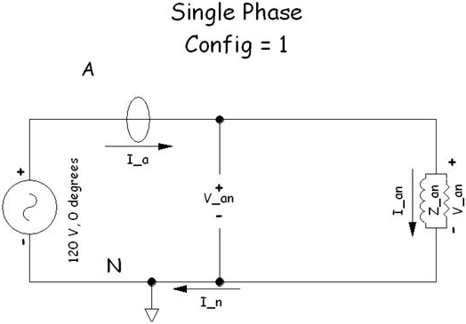
(Click image to expand/collapse display) |
| 2 | Split-phase with one voltage measurement and two current measurements. This configuration is typical of residential service-entry panels, as well as residential and commercial distribution panels. Split-phase configurations have two line (or “hot”) conductors plus a neutral conductor. | 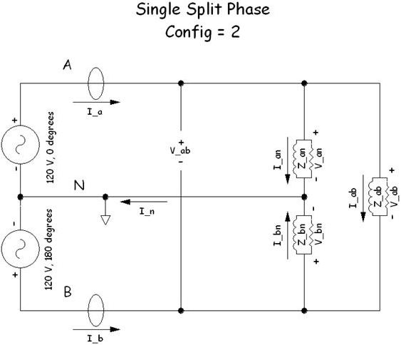
(Click image to expand/collapse display) |
| 3 | Three-phase ‘Y’, four-conductor, configurations with three voltage measurements and three current measurements. This configuration is typical of commercial entry panels and commercial distribution panels. The four conductors are three line (or “hot”) conductors plus a neutral conductor. | 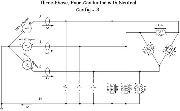
(Click image to expand/collapse display) |
Type: Constant
LineFrq (Line Frequency)
The expected line frequency in hertz. Valid entries are 60, 50, or a value between 2 and 20. A value between 2 and 20 indicates measurements from variable-frequency power, where LineFrq is the minimum frequency to be measured. Note that smaller values for LineFrq increase the measurement and processing time for this instruction. The maximum frequency for the variable-frequency mode is 480 Hz and independent of the 2- to 20-Hz minimum frequency.
Type: Constant
ChanV (Channel for Voltage Measurement)
The single-ended channel for the voltage measurement. For single- and split-phase configurations (ConfigAC = 1 or 2), the datalogger makes a voltage measurement at ChanV. For three-phase configurations (ConfigAC = 3), the datalogger makes three voltage measurements on increasing consecutive channels starting at ChanV.
Type: Constant
MultV (Transformer Multiplier)
The potential transformer multiplier represented as input Volts per output mVolts. A typical value is 115 V/333 mV (or 0.345345).
Type: Constant or Constant expression
MaxVrms (Maximum RMS Voltage)
The expected maximum ![]() RMS Root-mean square, or quadratic mean. A measure of the magnitude of wave or other varying quantities around zero. voltage to measure. MaxVrms is specified at the primary of the potential transformer, or equivalently, the non-logger side of the potential transformer. Typical values are 120 or 240. The datalogger uses MultV and MaxVrms to calculate which input range to use for the voltage measurement.
RMS Root-mean square, or quadratic mean. A measure of the magnitude of wave or other varying quantities around zero. voltage to measure. MaxVrms is specified at the primary of the potential transformer, or equivalently, the non-logger side of the potential transformer. Typical values are 120 or 240. The datalogger uses MultV and MaxVrms to calculate which input range to use for the voltage measurement.
Type: Constant
ChanI (Current Measurement Channel)
The single-ended channel for the current measurement. For single-phase configurations (ConfigAC = 1) with RepsI greater than 1, the datalogger makes multiple current measurements on increasing consecutive channels starting at ChanI. For split-phase configurations (ConfigAC = 2), the datalogger makes two current measurements on increasing consecutive channels starting at ChanI. For three-phase configurations (ConfigAC = 3), the datalogger makes three current measurements on increasing consecutive channels starting at ChanV.
Type: Constant
MultI (Transformer Multiplier)
The current transformer multiplier as input Amps per output mVolts. A typical value is 15 Amps/333 mV (or 0.045045).
Type: Constant or constant expression
MaxIrms (Maximum RMS Current)
The expected maximum ![]() RMS Root-mean square, or quadratic mean. A measure of the magnitude of wave or other varying quantities around zero. current to measure. MaxIrms is specified at the primary of the current transformer, or equivalently, the non-logger side of the current transformer. The datalogger uses MultI and MaxIrms to calculate which input range to use for the current measurement(s).
RMS Root-mean square, or quadratic mean. A measure of the magnitude of wave or other varying quantities around zero. current to measure. MaxIrms is specified at the primary of the current transformer, or equivalently, the non-logger side of the current transformer. The datalogger uses MultI and MaxIrms to calculate which input range to use for the current measurement(s).
Type: Constant
RepsI (Number of Current Measurements)
The number of current measurements to make on consecutive single-ended input channels. This parameter is used only in configuration 1 and is ignored by the datalogger for configurations 2 and 3.
Type: Constant
Results Returned
In each of the three configurations, DestAC may be a single-element variable or a dimensioned variable array. The ACPower instruction will store as many results as will fit in DestAC.
If the LineFrq value is between 2 and 20, inclusive, (i.e., the expected frequency is not known or "wild"), the phase (VPhaseI) and harmonic ratio (VHarmRatio) are not included in the results.
ConfigAC = 1
Returns a maximum of 3 + 4*RepsI values in the following order:
- Power(RepsI). The real power in Watts measured by the voltage and each current measurement, repeated to give RepsI values.
- MeasFrq. The measured voltage frequency in Hz.
- Voltage. The measured voltage in Volts rms.
- Current(RepsI). The measured current in Amps rms, repeated to give RepsI values.
- VphaseI(RepsI). The measured phase angle in radians that the voltage leads the current, repeated to give RepsI values. The cosine of VphaseI is the power factor.
- VharmRatio. The measured voltage harmonic distortion ratio given as the total harmonic content divided by the fundamental content at LineFrq Hz. VHarmRatio is unitless.
- IHarmRatio(RepsI). The measured current harmonic distortion ratio given as the total harmonic content divided by the fundamental content at LineFrq Hz, repeated to give RepsI values. IHarmRatio is unitless.
ConfigAC = 2
Returns a maximum of 12 values in the following order:
- TotPower. The total real power in Watts.
- Power(2). The real power in Watts measured by the voltage and each of two current measurements.
- MeasFrq. The measured voltage frequency in Hz.
- Voltage. The measured voltage in Volts rms.
- Current(2). The measured current in Amps rms, repeated to give two values.
- VphaseI(2). The measured phase angle in radians that the voltage leads the current, repeated to give two values. The cosine of VphaseI is the power factor.
- VharmRatio. The measured voltage harmonic distortion ratio given as the total harmonic content divided by the fundamental content at LineFrq Hz. VHarmRatio is unitless.
- IHarmRatio(2). The measured current harmonic distortion ratio given as the total harmonic content divided by the fundamental content at LineFrq Hz, repeated to give two values. IHarmRatio is unitless.
ConfigAC = 3
Returns a maximum of 20 values in the following order:
- TotPower. The total real power in Watts.
- Power(3). The real power in Watts measured for each of the three line conductors.
- MeasFrq. The measured voltage frequency in Hz.
- Voltage(3). The measured voltage in Volts rms for each of the three line conductors.
- Current(3). The measured current in Amps rms for each of the three line conductors.
- VphaseI(3). The measured phase angle in radians that the voltage leads the current for each of the three line conductors. The cosine of VphaseI is the power factor.
- VHarmRatio (3). The measured voltage harmonic distortion ratio given as the total harmonic content divided by the fundamental content at LineFrq Hz for each of the three line conductors. VHarmRatio is unitless.
- IHarmRatio(3). The measured current harmonic distortion ratio given as the total harmonic content divided by the fundamental content at LineFrq Hz for each of the three line conductors. IHarmRatio is unitless.