StrainCalc (Convert Strain Output)
The StrainCalc functions converts the mV/Volt output from a bridge measurement into microstrain (με).
Syntax
StrainCalc ( Dest, Reps, Source, BrZero, BrConfig, GageFactor, PoissonFactor )
The following program shows the use of the StrainCalc instruction.
'CR1000X Series Datalogger
'Declare Public Variables
Public Count, ZStrain, StMeas, Strain, Flag(8)
'Data Table STRAINS stores 1-minute
Average Strain
DataTable (STRAINS,True,-1)
DataInterval (0,1,Min,0)
Average (1,Strain,IEEE4,0)
EndTable
'Data Table ZERO_1 stores the "zero
Strain" measurement, which is
'the average of five
measurements
DataTable (ZERO_1,Count>4,10)
Average (1,ZStrain,IEEE4,0)
EndTable
'Subroutine to measure "zero Strain" when Flag(1) is low
Sub Zero
Count=0
Scan (1,Sec,0,5)
Count = Count+1
CallTable ZERO_1
NextScan
ZStrain=ZERO_1.ZStrain_AVG(1,1)
Flag(1)=True
EndSub
BeginProg
Scan (1,Sec,0,0)
If Flag(1) = False Then Call Zero
StrainCalc (Strain,1,StMeas,ZStrain,-1,2,0)
CallTable STRAINS
NextScan
EndProg
Remarks
The StrainCalc function calculates microstrain (με) using the appropriate formulae for the bridge configuration.
Parameters
Dest (Destination)
The Variable in which to store the results of the instruction. Right-click the parameter to display a list of defined variables.
If this instruction has a Repetitions parameter and it is greater than 1, the results are stored in an array with the variable name. The array must be dimensioned large enough to hold all of the values returned from all of the Reps.
Type: Variable or Array
Reps (Repetitions)
The number of repetitions for the measurement or instruction.
Type: Constant integer (or expression that evaluates as a constant).
If the Reps parameter is greater than 1, the Dest, Source, and BrZero parameters also must be variable arrays.
NOTE: If starting index is greater than 1 and Reps are greater than 1, use the syntax SourceArray(X)() to indicate the first array element to be used for the mVPerVolt, BrZero and GageFactor source arrays (where X is the starting index of the array, for example mVPerVolt(1)()). The empty set of parenthesis is the mechanism to automatically increment the source array index with each rep.
Source
The name of the Variable that is the input for the instruction. Right-click the parameter to display a list of defined variables.
Type: Variable
For the StrainCalc instruction, the Source parameter is the variable array containing the mV/Volt output(s) from the bridge measurement(s) that should be converted to microstrain. The Source is expected to be in millivolts out per volts in (the result of a full bridge measurement with a multiplier of 1 and an offset of 0).
BrZero (Zero Strain Value)
The variable array that holds the zero strain value (millivolts per volt) for the instruction. This value will be subtracted from subsequent strain readings so that the strain output values will be relative to the zero condition.
Type: Variable
BrConfig (Strain Configuration)
Used to determine which equation should be used for the strain calculation. A positive or negative code can be entered. A negative code reverses the output polarity.
Right-click the parameter to display a list.
| StrainCalc() BrConfig Code |
Configuration |
|---|---|
| 1 |
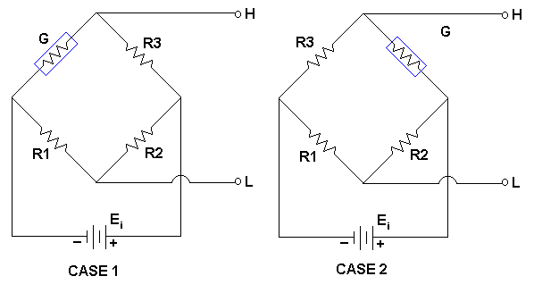
Quarter-bridge strain gage1:
CASE 1 - If a Campbell Scientific 4WFBXXX Terminal Input Module is utilized, the bridge set up is as depicted in Case 1. For this set up, a negative Option (-1) should be used for the datalogger to output positive strain values when the strain gage experiences positive strain. CASE 2 - If the excitation voltage polarity is reversed, or the output polarity is reversed, or if the bridge is configured as shown in Case 2, then a positive Code (1) should be used for the datalogger to output positive strain values when the strain gage experiences positive strain. |
| 2 |
Half-bridge strain gage1. One gage parallel to strain, the other at 90° to strain:
|
| 3 |
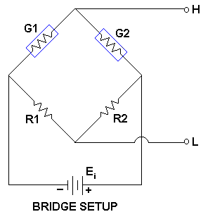
Half-bridge strain gage. One gage parallel to +ɛ, the other parallel to -ɛ1:
If a Campbell Scientific 4WFBXXX Terminal Input Module is utilized with the G2 gage wired to positive excitation and the G1 gage wired to ground, then the bridge set-up is as depicted above. For this set up, a negative Option (-2) should be used for the datalogger to output positive strain values when the G1 strain gage experiences positive strain. If the excitation voltage polarity is reversed, or the output polarity is reversed, or if the output data needs to be positive when the G2 strain gage sees positive strain, then a positive 2 should be inserted into the Code parameter. |
| 4 |
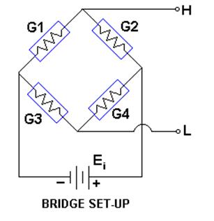
Full-bridge strain gage. Two gages parallel to +ɛ, the other two parallel to -ɛ1:
|
| 5 |
Full-bridge strain gage. Half the bridge has two gages parallel to +ɛ and -ɛ, and the other half to +nɛ and -nɛ 1:
|
| 6 |
Full-bridge strain gage. Half the bridge has two gages parallel to +ɛ and -nɛ , and the other half to -nɛ and +ɛ1:
This example assumes that the bridge (shown above) is set up such that the strain is considered to be positive when the G1 and G4 strain gauges experience positive strain (tension) while the G2 and G3 strain gauges experience negative strain (compression). In other words, when G1 and G4 increase in resistance (while G2 and G3 decrease in resistance), the strain is considered to be positive. The default setting for the output was configured for this bridge setup, and the datalogger's output strain data will be positive when the G1 and G4 strain gauges experiences positive strain. If the excitation voltage polarity is reversed, the output polarity is reversed, or if the output data needs to be positive when the G2 and G3 strain gauges experience positive strain, then Reverse should be clicked on. |
1Where
- n : Poisson's Ratio (0 if not applicable).
- GF: Gage Factor.
- Vr: 0.001 (Source-Zero) if BRConfig code is positive (+).
- Vr: –0.001 (Source-Zero) if BRConfig code is negative (–).
and where:
- "source": the result of the full-bridge measurement (X = 1000 • V1 / Vx) when multiplier = 1 and offset = 0.
- "zero": gage offset to establish an arbitrary zero.
Type: Constant
GageFactor (Gage Factor)
The name of the Variable that is the gage factor for the instruction.
The GageFactor can be entered as a constant that will be used for all repetitions or as a variable array that is loaded with the individual gage factors for each Rep. To use an array, enter the parameter as ArrayName() without an element number specified in the parentheses.
Type: Variable
PoissonFactor (Poisson Factor)
The name of the Variable that is the Poisson factor for the instruction. When using Codes 2, 5, or 6, enter the Poisson Ratio of the strained material. Enter 0 if the PoissonRatio (ⱱ) does not apply to the configuration.
Type: Variable


