CELL200-series to RF
This type of network is useful when a single data logger is not located close enough to a reliable cellular signal. To overcome this distance, use radios to establish connectivity with the cellular network.
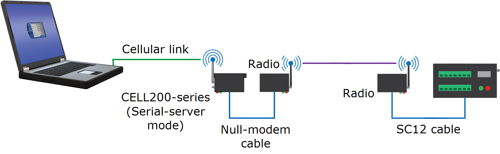
CELL200-series physical setup
-
Connect the CELL200-series and radio RS-232 ports using an RS-232 pin-to-pin null-modem cable.
-
Connect the cellular and radio antennas, if they are not already connected.
-
Apply DC power to the CELL200-series and radio.
Configure the CELL200-series as a serial server
-
Connect a USB cable between a USB port on your computer and the USB port on the CELL200 series.
-
Starting with the default settings, open a web browser and go to: cell.linktodevice.com.
NOTE:Cellular service must be setup before configuring the CELL200-series.
-
If the data logger has been assigned a public static IP address, on the Settings > General tab:
-
Enter the APN as assigned by your service provider.
-
Change Mode from PPP to Serial Server.
-
Click Apply to save the changes and then close the browser tab.
-
-
If the data logger has been assigned a private dynamic IP address and you are using the Konect PakBus Router service, on the Settings tab:
-
General tab > Enter the APN as assigned by your service provider.
-
General tab > Change Mode from PPP to Serial Server/Client.
-
Serial Mode Setup > URL > Enter the Konect PakBus Router address.
-
Serial Mode Setup > Port Number > Enter the Konect PakBus Router port number.
NOTE:Konect PakBus Router connections through a CELL200 series modem do not support a TCP Password. Contact Campbell Scientific support for more information.
-
Configure radio connected to the CELL200-series
Connect a USB cable between a USB port on your computer and the USB port on the radio that will be connected to the CELL200 series. Either RF407-series or RF451/452 radios can be used. See those product manuals for additional details.
RF407-series
-
Connect to the radio in Device Configuration Utility.
-
Click the Factory Defaults button at the bottom of the Deployment window.
-
On the Main tab set Active Interface to RS-232.
-
Click Apply to save the changes.
RF451/452
-
Connect to the radio in Device Configuration Utility.
-
Click the Factory Defaults button at the bottom of the Deployment window.
-
On the Deployment tab set:
-
Active Interface to RS-232
-
Radio Operation Mode to Gateway (previously called Master)
NOTE:There can only be one Gateway in an RF451/452 network.
-
-
Click Apply to save the changes.
Configure radio connected to the data logger
-
Using an SC12 cable connect the data logger CS I/O port to the radio CS I/O port.
-
Connect a USB cable between a USB port on your computer and the radio USB port.
RF407-series
-
Connect to the radio in Device Configuration Utility.
-
Click the Factory Defaults button at the bottom of the Deployment window.
-
Click Apply to save the changes.
RF451/452
-
Connect to the radio in Device Configuration Utility.
-
Click the Factory Defaults button at the bottom of the Deployment window.
-
On the Deployment tab keep the defaults and confirm:
-
Active Interface is CS I/O SDC
-
SDC Addres is 7
-
Radio Operation Mode is Endpoint (previously called Slave)
-
-
Click Apply to save the changes.
Configure the data logger
-
Connect a USB cable between a USB port on your computer and the data logger USB port.
-
Connect to the data logger in Device Configuration Utility.
-
Click the Factory Defaults button at the bottom of the Deployment window.
-
On the Datalogger tab verify or change the PakBus address.
-
Default address is 1.
-
If using Konect PakBus Router, verify the address assigned here matches the address you setup for the data logger in Konect PakBus Router.
-
-
On the Com Ports Settings tab set:
-
ComPort to CS I/O SDC7
-
Beacon Interval to 60 (seconds)
-
-
Click Apply to save the changes and then close Device Configuration Utility.
Setup LoggerNet
-
In the LoggerNet Setup screen, click Add Root and select IPPort. Enter the CELL200-series IP address and
 port number A port number is a way to identify a specific process or service to which a network message is to be forwarded when it arrives at the NL200/NL201. For example, FTP often uses port 21 while HTTP uses port 80.. The IP address and port number are input on the same line separated by a colon. IPv6 addresses will need to be enclosed in square brackets when specifying a port number. An IPv4 address may look like 192.168.1.100:3001. An IPv6 address may look like [2001:db8::1234:5678]:3001. A fully qualified host name entry may look like yourlogger.com:3001. In serial server mode, the default port number is 3001.
If you are using a Konect PakBus Router use the address of the Konect PakBus Router followed by a colon and the port number of the PakBus router.
-
Add PakBusPort (PakBus Loggers).
-
Add a PakBus Router (pbRouter). The default PakBus address for the Konect PakBus Router is 4070. Click Close.
-
Add the data logger and enter its PakBus address. If using a Konect PakBus Router ensure that the PakBus address matches both that of the data logger and the configuration you setup with your Konect PakBus Router.
-
Click Apply to save the changes.
-
You are now ready to connect to your data logger using LoggerNet. Select Main and Connect on the LoggerNet toolbar, select the data logger from the Stations list, then Connect. From there, you can view and collect data, or manage data logger settings.