Direct RS-232 connection
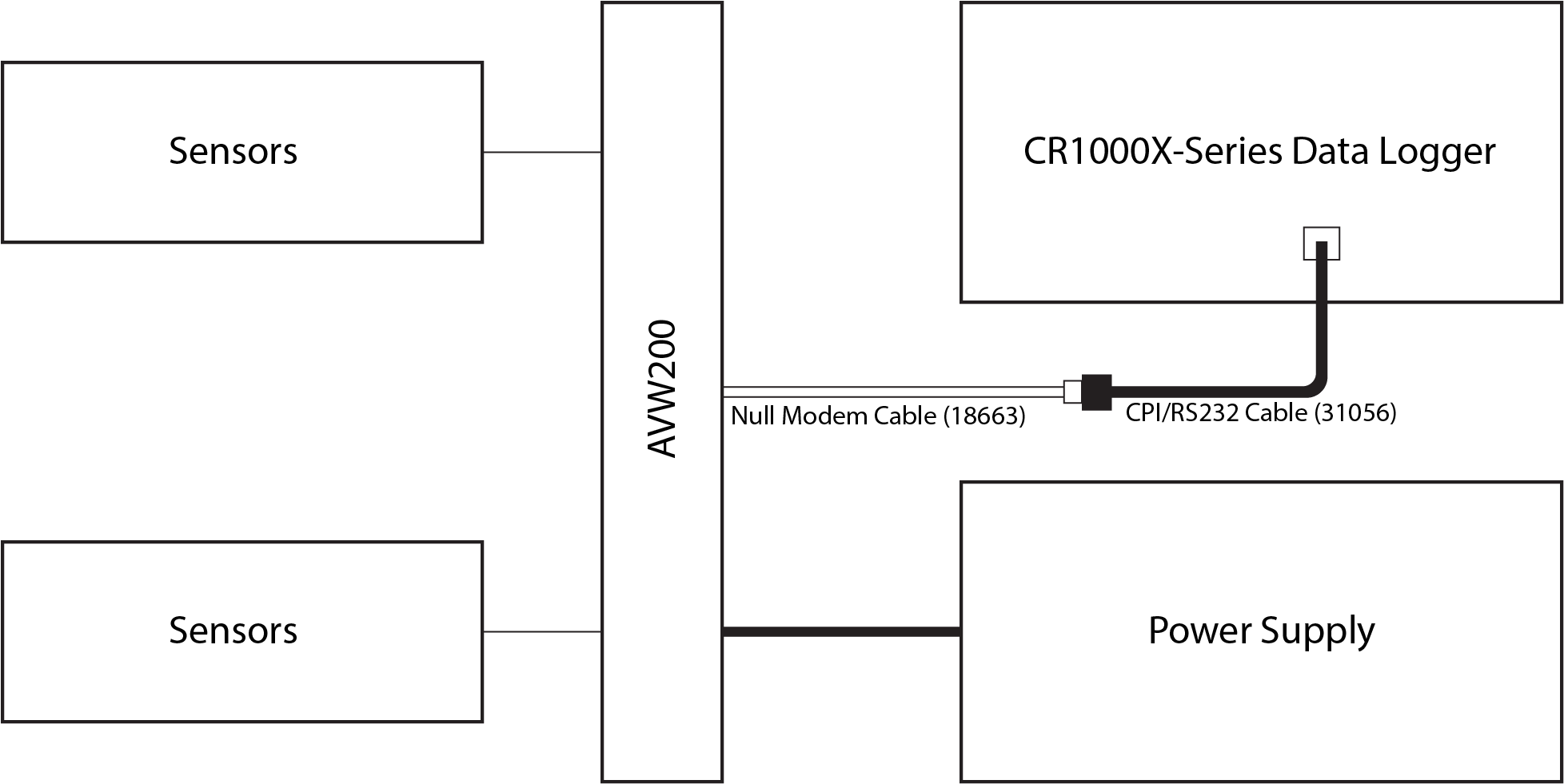
For this simple configuration, the can be used straight from the box without changing settings in Device Configuration Utility. Sensor(s) are attached directly to the , which is connected directly to the data logger via a DB9 pin-to-pigtail serial cable or null modem cable. The serial cable pigtail end connects to data logger control port pairs (C1/C2 through C7/C8). The null modem cable has a DB9 connector to attach to the data logger RS-232 port.
The CR1000X-Series features an RS-232/CPI port that requires a 31056 cable (with a female DB9 socket) to connect the data logger's RS-232/CPI port to the 18633 null modem cable.
The following steps are used to measure the sensor(s):
-
Attach the vibrating-wire sensor(s) to the as shown in Wiring for sensor connections.
-
Use the serial cable to attach the to a control port pair (such as C1/C2, C3/C4, C5/C6, or C7/C8) on the data logger, or use the null modem cable to attach the to the RS-232 port on the data logger.
-
Connect one end of the power cable to the 12V and G terminals on the ; connect the other end to the 12V and G terminals on the data logger or external power supply. See Power and ground and Data logger wiring for a direct connection.
-
Create a CRBasic program that includes an
AVW200()instruction for each sensor.For example, the following
AVW200()instructions can be used to measure two sensors:AVW200(Result,ComC1,200,200,Dst(1,1),1,1,1,1000,3500,2,_60HZ,1,0)AVW200(Result,ComC1,200,200,Dst(2,1),2,1,1,1000,3500,2,_60HZ,1,0)
where:
connects to data logger control ports C1/C2 via a serial cable (option ComC1)
Begin frequency = 1000
End frequency = 3500
Excitation voltage = 12 VDC peak to peak (option 2)
Refer to Programming with the AVW200() instruction for a thorough description of the AVW200() instruction and its parameters. Refer to Direct RS-232 connection with two sensors for a complete example program that measures two vibrating-wire sensors with no multiplexer.