Connectors
The following is the connector panel for the AtmosVue 30.
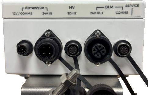
The sensor is equipped with five IP66-rated connectors for power, communication, and auxiliary functions. Please note that the IP66 rating is only maintained when a connector is properly mated with either a cable or a protective cap.
-
The first connector provides the main power and serial communications, supplying 9 to 30 VDC to the internal electronics. A 5-meter cable is supplied for this connection.
-
The second connector supplies 24 V power to the hood heaters and is also fitted with a 5-meter cable.
-
The third connector is used for the AtmosVue-HV temperature and humidity probe.
-
The fourth connector delivers 24 V power to the AtmosVue-BLM Background Luminance Meter.
-
The fifth connector provides serial communication and 12 V power to the AtmosVue-BLM.
To prevent damage to the noise filters on the hood heater inputs, ensure correct wiring: if the heater uses AC voltage, connect the neutral wire (if present) to the black 0V cable and the live wire to the red cable. The black 0V connection must remain within 5 V of the main electronics ground or any other 0 V reference in the system to maintain proper grounding and avoid potential damage.
To use these connections, you may either use the supplied cables or fabricate your own using the guidelines provided in this manual. If you plan to build custom cables, we recommend contacting Campbell Scientific for assistance in selecting the appropriate cable type to ensure compatibility and optimal performance.
Campbell Scientific recommends using 24 AWG (0.205 mm²) or larger cables for communications and 12V power lines, and 16 AWG (1.31 mm²) or larger for 24V hood heater cables. These guidelines are designed to ensure reliable voltage levels at the equipment under all operating conditions for cable lengths up to 20 meters.
For installations exceeding 20 meters, it is essential to perform voltage drop calculations to ensure proper system performance and to avoid under-voltage issues.
|
Connector 1 – Main communications and 12 V power |
|||
|---|---|---|---|
| Pin | Function | Color1 | Notes |
|
1 |
RX |
White |
|
|
2 |
- |
Brown |
|
|
3 |
0V comms |
Green |
100 Ohm resistor to 0V |
|
4 |
- |
Yellow |
|
|
5 |
12V |
Gray |
Main 12 V power input2 |
|
6 |
- |
Pink |
|
|
7 |
TX |
Blue |
|
|
8 |
0V |
Red |
Main 0V power2 |
|
Connector 2—Main 24V hood heater power input |
|||
|---|---|---|---|
|
Pin |
Function |
Color |
Notes |
|
1 |
- |
- |
Not connected |
|
2 |
24V |
Red |
24V power input (16 AWG recommended) |
|
3 |
0V |
Black |
Power return (16 AWG recommended) |
|
4 |
Screen |
- |
Shield/earth connection |
|
Connector 3—SDI-12 temperature and humidity probe connector |
|||
|---|---|---|---|
|
Pin |
Function |
Internal Color1 |
Notes |
|
1 |
|
White |
|
|
2 |
|
Brown |
|
|
3 |
|
Green |
|
|
4 |
|
Yellow |
|
|
5 |
12V |
Grey |
This is a 12V power output |
|
6 |
SDI-12 comms |
Pink |
|
|
7 |
|
Blue |
|
|
8 |
0V |
Red |
This is the main 0V |
|
Connector 4—AtmosVue Background Luminance Meter (BLM) 24V hood heater power output (RD24 Female Connector [3 way + earth]) |
|||
|---|---|---|---|
|
Pin |
Function |
Color |
Notes |
|
1 |
- |
- |
Not connected |
|
2 |
24V |
Red |
24V output |
|
3 |
0V |
Black |
|
|
4 |
Screen |
- |
|
|
Connector 5—AtmosVue Background Luminance Meter (BLM) main communications and 12V output (M12 Female A coded 8 way connector) |
|||
|---|---|---|---|
|
Pin |
Function |
Internal Color1 |
Notes |
|
1 |
RX |
White |
|
|
2 |
|
Brown |
|
|
3 |
0V comms |
Green |
|
|
4 |
|
Yellow |
|
|
5 |
12V |
Grey |
This is a 12V power to the BLM |
|
6 |
|
Pink |
|
|
7 |
TX |
Blue |
|
|
8 |
0V |
Red |
This is the main 0V |