Step 3 – Choose Sensors to Monitor
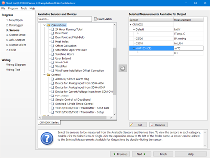
In step 3, you tell Short Cut which sensors you’ll be measuring. Short Cut organizes sensors into application groups:
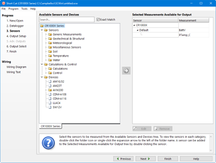
Some major groups have subgroups. Double-clicking the Meteorological group folder shows several subgroups of meteorological sensors. Double-click a subgroup to show the available sensors. Refer to the documentation for your sensors for the name of the sensors you have. If your sensor is not shown, you may be able to measure it with a generic measurement. Contact your Campbell Scientific application engineer for more assistance, if needed.
You “add” sensors to your program by double-clicking them or selecting them and clicking the arrow in the middle of the screen. Most sensors will require you to at least review the default settings for that measurement, including the measurement name, units, etc. An example of choosing the CS105 Barometric Pressure Sensor is below.
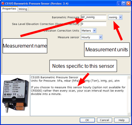
Note that this sensor not only offers a custom name field and units, but also allows you to correct for sea level, a common practice in measuring atmospheric pressure. In the middle of the screen, look over the notes (or refer to the Help for this sensor), for this sensor may require other sensors or have limitations. When you choose OK, Short Cut adds the necessary instructions with appropriate multipliers and offsets.
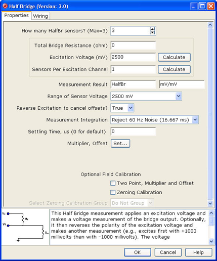
In some cases, multiple sensors of the same type can be added at one time. These sensors will have a How many sensors? parameter as the first parameter on the form as shown below. The maximum number of sensors that can be added will be indicated. The maximum will vary, depending upon the sensor and the number of other sensors already configured in the program. If the sensor form includes calibration and/or conversion parameters (e.g., multiplier, offset, gage factor), there will be a Set button next to these parameters. Pressing this button will allow you to set unique values for each sensor.
Click on the Wiring tab of a sensor’s parameter form to show the wiring for the sensor (or the first sensor in a sensor group).
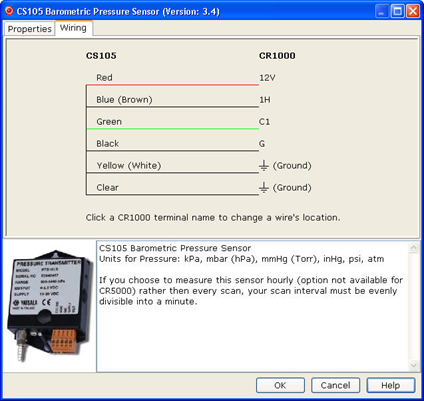
Each wire’s caption/color is shown on the left side of the wire. The location where the wire will be connected to the device is shown on the right side (under the device). You can change a caption/color by clicking on the caption/color label. A wiring location can also be changed by clicking on the wiring location.
NOTE: Changes to the wiring location for a sensor group can only be made when the group is first added. To make changes to a wiring location at a later time, you will need to change the number of sensors to one, press OK, reopen the parameter form, make the desired wiring location changes, and then change the number of sensors back to the desired number.
NOTE: Not all sensors support changes to the wire caption/color and wiring location. When hovering over a wire caption/color or wiring location, the mouse cursor will change to indicate that the property can be changed. Changes are generally supported for generic sensors and other sensors that do not use special wiring connections.
At any time, you may choose a measurement label on the right side of the Sensors screen and edit it or remove it.
In addition to actual sensors, Short Cut provides functionality to perform various calculations and effect some simple control:
Some of these calculations may require additional sensors, or sensor measurements stored in particular units. See the help for each calculation to determine the necessary inputs. Note that there is also a User Entered calculation available in the Calculations folder. With it you can enter your own custom calculation.
In the example below, a new measurement, AirTF, is being created by performing calculations on an existing measurement, AirTC:
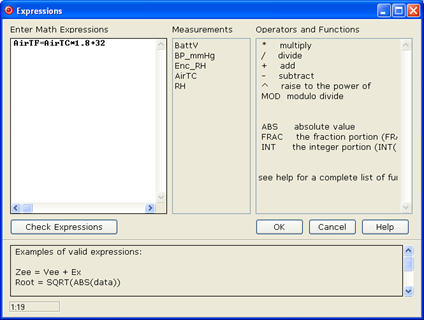
Refer to the online help for complete information on creating User Calculation.
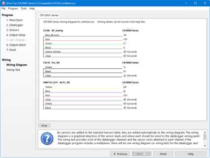
Short Cut provides you with a wiring diagram by clicking on Wiring Diagram on the left side of the Sensors window. In the example below, Short Cut was told to measure a CS106 Barometric Pressure sensor, a CS210 enclosure relative humidity sensor, and an HMP155 Air Temperature and Relative Humidity sensor. Each sensor was allocated the necessary terminals. Short Cut will not let you add more sensors than there are terminals on that datalogger or device. You can print this diagram (or the textual equivalent) by choosing the Print button. Many users find it handy to leave a printed wiring diagram in the enclosure with the datalogger in case a sensor has to be replaced.
Short Cut can also create programs for dataloggers using a variety of interface devices, including multiplexers and special interfaces for sensors. Add these devices by selecting them from the Devices folder in the Available Sensors and Devices tree.
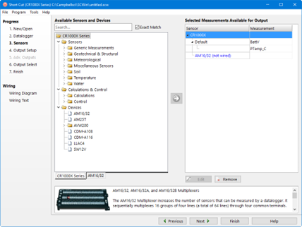
Once you’ve added a device, such as the AM16/32 multiplexer, a tab is added to the screen for that device, and the sensors available for that device are shown:
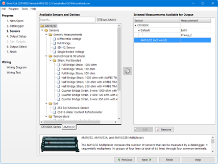
You can then add sensors to that device just as you would to the main datalogger.
Note that, once you add a sensor to a multiplexer, it may limit what kind of sensors can be added thereafter, as each sensor on the multiplexer must share the same wiring between the multiplexer and the datalogger.
After adding all the desired sensors, click Next.