Communications ports
The data logger is equipped with ports that allow communications with other devices and networks, such as:
- Computers
- Smart sensors
 Modbus Communications protocol published by Modicon in 1979 for use in programmable logic controllers (PLCs). and DNP3 outstation Distributed Network Protocol is a set of communications protocols used between components in process automation systems. Its main use is in utilities such as electric and water companies. networks
- Ethernet
- Modems
- Campbell Scientific PakBus ™ A proprietary communications protocol developed by Campbell Scientific to facilitate communications between Campbell Scientific devices. Similar in concept to IP (Internet Protocol), PakBus is a packet-switched network protocol with routing capabilities. A registered trademark of Campbell Scientific, Inc.™ networks
- Other Campbell Scientific data loggers
- GRANITE Measurement Modules
- Vehicles using CAN bus (GRANITE 10 only)
Campbell Scientific data logger communications ports include:
- CS I/O
- CPI/RS-232
- EPI
- CAN bus (GRANITE 10 only)
- USB Device
- USB Host
- Ethernet
- C terminals
USB device port
The USB device port supports communicating with a computer through ![]() data logger support software LoggerNet, RTDAQ, and PC400 - these Campbell Scientific software applications include at least the following functions: data logger communications, downloading programs, clock setting, and retrieval of measurement data. or through virtual Ethernet (
data logger support software LoggerNet, RTDAQ, and PC400 - these Campbell Scientific software applications include at least the following functions: data logger communications, downloading programs, clock setting, and retrieval of measurement data. or through virtual Ethernet (![]() RNDIS Remote Network Driver Interface Specification - a Microsoft protocol that provides a virtual Ethernet link via USB.), and provides 5 VDC power to the data logger (powering through the USB port has limitations - details are available in the specifications).
RNDIS Remote Network Driver Interface Specification - a Microsoft protocol that provides a virtual Ethernet link via USB.), and provides 5 VDC power to the data logger (powering through the USB port has limitations - details are available in the specifications).
USB host port
USB host provides portable data storage on a USB thumb drive. A FAT32-formatted USB thumb drive can be inserted into the host port and will show up as a drive (USB:) in file-related operations. Measurement data is stored on USB: as discrete files by using the TableFile() instruction. Files on USB: can be collected by inserting the thumb drive into a computer and copying the files.
USB: can be used in all CRBasic file-access-related instructions. Because of data reliability concerns in non-industrial rated drives, this drive is not intended for long-term unattended data storage. Rather, configure Tablefile() for milking (plug-and-pull) to periodically collect data. Files on USB: are not affected by program recompilation or formatting of other drives.
See the CRBasic Editor help for detailed instruction information and program examples:
![]()
![]()
Ethernet port
The RJ45 10/100/1000 Ethernet port is used for IP communications.
C terminals for communications
C terminals are configurable for the following communications types:
- SDI-12
- RS-232
- RS-422
- RS-485
- TTL (0 to 5 V)
- LVTTL (0 to 3.3 V)
- SDM
Some communications types require more than one terminal, and some are only available on specific terminals. See Communications specifications for more information.
SDI-12 ports
![]() SDI-12 Serial Data Interface at 1200 baud. Communications protocol for transferring data between the data logger and SDI-12 compatible smart sensors. is a 1200 baud protocol that supports many smart sensors.
SDI-12 Serial Data Interface at 1200 baud. Communications protocol for transferring data between the data logger and SDI-12 compatible smart sensors. is a 1200 baud protocol that supports many smart sensors.
For more information, see SDI-12 communications.
RS-232, RS-422, RS-485, TTL, and LVTTL ports
RS-232, RS-422, RS-485, TTL
- Reading sensors with serial output
- Creating a multi-drop network
- Communications with other data loggers or devices over long cables
The maximum cable length for RS-232 communication is typically limited to 50 feet (15 meters) at 19200 baud. Higher baud rates may result in shorter transmission distances due to signal degradation.
RS-485 supports a theoretical maximum point-to-point communication distance of 1200 meters (4000 feet). To achieve this distance, it's essential to use well-shielded and insulated cable, ensure careful installation, apply bus termination, and maintain low data rates (baud) of less than 115200 bps.
Configure C terminals as serial ports using ![]() Device Configuration Utility Software tool used to set up data loggers and peripherals, and to configure PakBus settings before those devices are deployed in the field and/or added to networks. Also called DevConfig. or by using the
Device Configuration Utility Software tool used to set up data loggers and peripherals, and to configure PakBus settings before those devices are deployed in the field and/or added to networks. Also called DevConfig. or by using the SerialOpen() CRBasic instruction. Terminals are configured in pairs for TTL,
RS-232 ports are not isolated.
SDM ports
SDM is a protocol proprietary to Campbell Scientific that supports several Campbell Scientific digital sensor and communications input and output expansion peripherals and select smart sensors. It uses a common bus and addresses each node.SDMBeginPort() instruction.
See also Communications specifications.
CS I/O port
One nine-pin port, labeled CS I/O, is available for communicating with a computer through Campbell Scientific communications interfaces, modems, and peripherals. Campbell Scientific recommends keeping CS I/O cables short (maximum of a few feet). See also Communications specifications.
|
CS I/O pinout |
|||
|---|---|---|---|
| Pin number |
Function | Input (I) Output (O) |
Description |
| 1 | 5 VDC | O | 5 VDC: sources 5 VDC, used to power peripherals. |
| 2 | SG | Signal ground: provides a power return for pin 1 (5V), and is used as a reference for voltage levels. | |
| 3 | RING | I | Ring: raised by a peripheral to put the GRANITE 9/10 in the telecom mode. |
| 4 | RXD | I | Receive data: serial data transmitted by a peripheral are received on pin 4. |
| 5 | ME | O | Modem enable: raised when the GRANITE 9/10 determines that a modem raised the ring line. |
| 6 | SDE | O | Synchronous device enable: addresses synchronous devices (SD); used as an enable line for printers. |
| 7 | CLK/HS | I/O | Clock/handshake: with the SDE and TXD lines addresses and transfers data to SDs. When not used as a clock, pin 7 can be used as a handshake line; during printer output, high enables, low disables. |
| 8 | 12 VDC | Nominal 12 VDC power. Same power as 12V and SW12 terminals. | |
| 9 | TXD | O | Transmit data: transmits serial data from the data logger to peripherals on pin 9; logic-low marking (0V), logic-high spacing (5V), standard-asynchronous ASCII: eight data bits, no parity, one start bit, one stop bit. User selectable baud rates: 300, 1200, 2400, 4800, 9600, 19200, 38400, 115200. |
CPI/RS-232 port
The data logger includes one RJ45 module jack labeled ![]() RS-232 Recommended Standard 232. A loose standard defining how two computing devices can communicate with each other. The implementation of RS-232 in Campbell Scientific data loggers to computer communications is quite rigid, but transparent to most users. Features in the data logger that implement RS-232 communications with smart sensors are flexible./CPI.
RS-232 Recommended Standard 232. A loose standard defining how two computing devices can communicate with each other. The implementation of RS-232 in Campbell Scientific data loggers to computer communications is quite rigid, but transparent to most users. Features in the data logger that implement RS-232 communications with smart sensors are flexible./CPI. ![]() CPI CPI is a proprietary interface for communications between Campbell Scientific data loggers and Campbell Scientific CDM peripheral devices. It consists of a physical layer definition and a data protocol. is a proprietary interface for communications between Campbell Scientific data loggers and Campbell Distributed Modules (CDMs) such as the GRANITE-Series peripheral devices and smart sensors. It consists of a physical layer definition and a data protocol. CDM devices are similar to Campbell Scientific
CPI CPI is a proprietary interface for communications between Campbell Scientific data loggers and Campbell Scientific CDM peripheral devices. It consists of a physical layer definition and a data protocol. is a proprietary interface for communications between Campbell Scientific data loggers and Campbell Distributed Modules (CDMs) such as the GRANITE-Series peripheral devices and smart sensors. It consists of a physical layer definition and a data protocol. CDM devices are similar to Campbell Scientific ![]() SDM Synchronous Device for Measurement. A processor-based peripheral device or sensor that communicates with the data logger via hardwire over a short distance using a protocol proprietary to Campbell Scientific. devices in concept, but the CPI bus enables higher data-throughput rates and use of longer cables. Some GRANITE devices may require more power to operate in general than do SDM devices. Consult the manuals for GRANITE modules for more information.
SDM Synchronous Device for Measurement. A processor-based peripheral device or sensor that communicates with the data logger via hardwire over a short distance using a protocol proprietary to Campbell Scientific. devices in concept, but the CPI bus enables higher data-throughput rates and use of longer cables. Some GRANITE devices may require more power to operate in general than do SDM devices. Consult the manuals for GRANITE modules for more information.
CPI/RS-232 port is not isolated.
CPI port power levels are controlled automatically by the GRANITE 9/10:
- Off: Not used.
- High power: Fully active.
- Low-power standby: Used whenever possible.
- Low-power bus: Sets bus and modules to low power.
When used with a Campbell Scientific RJ45-to-DB9 converter cable, the CPI/RS-232 port can be used as an RS-232 port. It defaults to 115200 bps (in autobaud mode), 8 data bits, no parity, and 1 stop bit. Use Device Configuration Utility or the SerialOpen() CRBasic instruction to change these options.
|
RS-232/CPI pinout |
|
|---|---|
| Pin number | Description |
| 1 | RS-232: Transmit (Tx) |
| 2 | RS-232: Receive (Rx) |
| 3 | 100 Ω Res Ground |
| 4 | CPI: Data |
| 5 | CPI: Data |
| 6 | 100 Ω Res Ground |
| 7 | RS-232 CTS CPI: Sync |
| 8 | RS-232 DTR CPI: Sync |
| 9 | Not Used |
EPI port
The data logger includes two RJ45 module jacks labeled EPI. Ethernet Peripheral Interface (EPI) is a proprietary interface for communications between Campbell Scientific data loggers and Campbell Distributed Modules (CDMs) such as the GRANITE-Series peripheral devices and smart sensors. EPI expands the functionality or channel count of the GRANITE 9/10. This communications connection satisfies the tight timing requirements imposed on independent GRANITE Measurement Modules that are working together as part of a measurement and control system.
The underlying communications of EPI are built using TCP/IP. More specifically, the IEEE 1588 protocol is implemented at the lowest hardware levels for synchronization of device clocks across the entire network. This accomplishes tighter device synchronization and 100-times the data throughput of CPI. The additional power, cost, and complexity are warranted for fast sampling applications.
CAN port (GRANITE 10 only)
The CAN (Controller Area Network) physical layer is a differential signal that is generally a twisted pair. The GRANITE 10 has 4 general purpose CAN ports, CAN 2.0 up to 1 Mbps, or CAN FD up to 5 Mbps. They can be accessed either by the screw terminals, or the 15-pin connector; they are electrically connected. Wire the differential signal (H and L) into the screw terminals, or use a custom cable and the 15-pin connector.
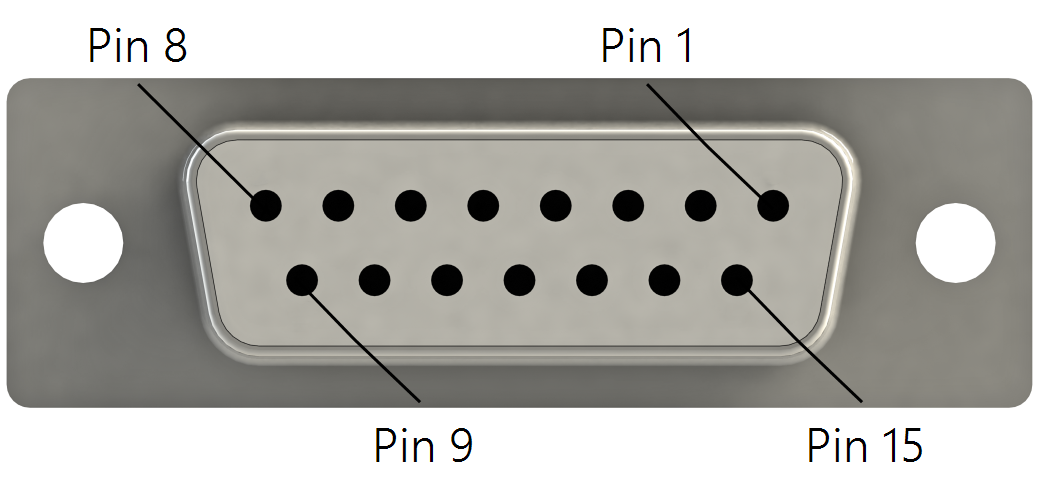
|
CAN bus pinout |
|
|---|---|
| Pin Number | Description |
| 1 | CAN1 H |
| 2 | CAN1 L |
| 3 | RG1 |
| 4 | CAN2 H |
| 5 | CAN2 L |
| 6 | RG2 |
| 7 | CAN3 H |
| 8 | CAN3 L |
| 9 | RG3 |
| 10 | CAN4 H |
| 11 | CAN4 L |
| 12 | RG4 |
| 13 | Not used |
| 14 | Not used |
| 15 | Not used |