Wiring panel and terminal functions
The GRANITE 9/10 wiring panel provides ports and removable ![]() terminals Point at which a wire (or wires) connects to a wiring panel or connector. Wires are usually secured in terminals by screw- or lever-and-spring actuated gates with small screw- or spring-loaded clamps. for connecting sensors, power, and communications devices. It is protected against surge, over-voltage, over-current, and reverse power. The wiring panel is the interface to most data logger functions so studying it is a good way to get acquainted with the data logger. Functions of the terminals are broken down into the following categories:
terminals Point at which a wire (or wires) connects to a wiring panel or connector. Wires are usually secured in terminals by screw- or lever-and-spring actuated gates with small screw- or spring-loaded clamps. for connecting sensors, power, and communications devices. It is protected against surge, over-voltage, over-current, and reverse power. The wiring panel is the interface to most data logger functions so studying it is a good way to get acquainted with the data logger. Functions of the terminals are broken down into the following categories:
- Pulse counting
- Communications
- Digital I/O
- Power input
- Power output
- Power ground
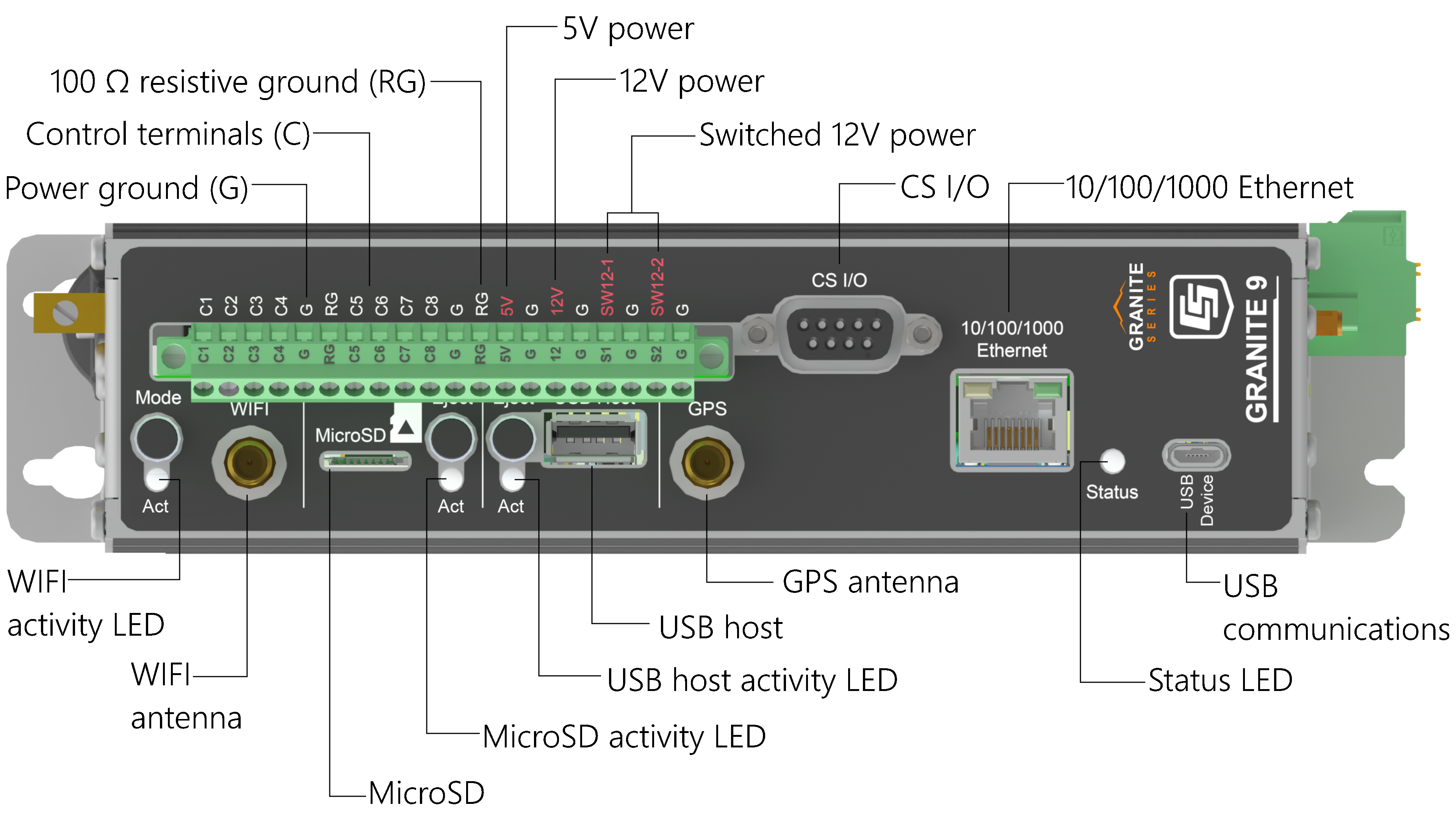
GRANITE 9 Wiring panel

GRANITE 9

GRANITE 10 Wiring panel
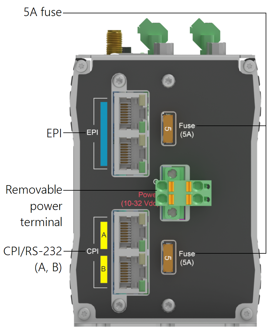
GRANITE 10
|
Pulse counting terminal functions |
|
|---|---|
| C1-C8 | |
| Switch-Closure | ✓ |
| High Frequency | ✓ |
| Quadrature | |
Conflicts can occur when a control port pair is used for different instructions (TimerInput(), PulseCount(), SDI12Recorder(), WaitDigTrig()). For example, if C1 is used for SDI12Recorder(), C2 cannot be used for TimerInput(), PulseCount(), or WaitDigTrig().
|
Voltage output terminal functions |
|||||
|---|---|---|---|---|---|
| C1-C8 | 12V | SW12-1 | SW12-2 | 5V | |
| 3.3 VDC | ✓ | ||||
| 5 VDC | ✓ | ✓ | |||
|
+POWER IN up to 12 VDC |
✓ | ✓ | ✓ | ||
|
Communications terminal functions |
||||||||||
|---|---|---|---|---|---|---|---|---|---|---|
| C1 | C2 | C3 | C4 | C5 | C6 | C7 | C8 | RS-232/ CPI |
GRANITE 10 only |
|
| SDI-12 | ✓ | ✓ | ✓ | |||||||
| GPS Time Sync | Tx | Rx | Tx | Rx | Tx | Rx | Tx | Rx | ||
|
TTL1 0-5 V |
Tx | Rx | Tx | Rx | Tx | Rx | Tx | Rx | ||
|
LVTTL1 0-3.3 V |
Tx | Rx | Tx | Rx | Tx | Rx | Tx | Rx | ||
| RS-232 | Tx | Rx | Tx | Rx | Tx | Rx | Tx | Rx | ✓ | |
| RS-485 (Half Duplex) |
A- | B+ | A- | B+ | A- | B+ | A- | B+ | ||
| RS-485 (Full Duplex) |
Tx- | Tx+ | Rx- | Rx+ | Tx- | Tx+ | Rx- | Rx+ | ||
| I2C | SCL | SDA | SCL | SDA | SCL | SDA | SCL | SDA | ||
| SPI | SCLK | COPI | CIPO | SCLK | COPI | CIPO | ||||
| SDM | Data | Clk | Enabl | |||||||
| CPI/ CDM |
✓ | |||||||||
| CAN bus | ✓ | |||||||||
1TTL and LVTTL are configured with the CommsMode option of the SerialOpen instruction in CRBasic. |
||||||||||
|
Digital I/O terminal functions |
|
|---|---|
| C1-C8 | |
| General I/O | ✓ |
| Pulse-Width Modulation Output | ✓ |
| Timer Input | ✓ |
| Interrupt | ✓ |