CAN (GRANITE 10 only)
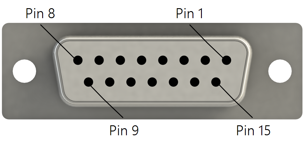
The CAN (Controller Area Network) physical layer is a differential signal that is generally a twisted pair. The GRANITE 10 has 4 general purpose CAN ports, CAN 2.0 up to 1 Mbps, or CAN FD up to 5 Mbps. They can be accessed either by the screw terminals, or the 15-pin connector; they are electrically connected. Wire the differential signal (H and L) into the screw terminals, or use a custom cable and the 15-pin connector.
|
CAN bus pinout |
|
|---|---|
| Pin Number | Description |
| 1 | CAN1 H |
| 2 | CAN1 L |
| 3 | RG1 |
| 4 | CAN2 H |
| 5 | CAN2 L |
| 6 | RG2 |
| 7 | CAN3 H |
| 8 | CAN3 L |
| 9 | RG3 |
| 10 | CAN4 H |
| 11 | CAN4 L |
| 12 | RG4 |
| 13 | Not used |
| 14 | Not used |
| 15 | Not used |
CRBasic instructions
In the GRANITE 10 program, CAN functionality is accessed with the CANPortOpen(), CANRead(), CANFilterRead(), CANWrite(), CANFDPortOpen(), CANFDRead(), CANFDFilterRead(), and CANFDWrite() instructions. Both Short Cut and CRBasic support DBC files for vehicle CAN integration. If a protocol other than DBC is needed, use CANRead() and CANWrite() to implement it. See the CRBasic Editor help for detailed instruction information and program examples: ![]()
![]()
CANPortOpen() / CANFDPortOpen
These instruction configure the bit rate and other physical parameters of the specified CAN port. The instruction only needs to be executed once per port, and should located after BeginProg(), and before Scan().
CANPortOpen() has the following parameters:
CANPort
|
Specifies which of the 4 CAN ports to use. |
BitRate
|
Specifies the bit rate in Kbps that is used for communication on the CAN port. |
SilentMode
|
Specifies whether messages can be received without acknowledgment. |
Termination
|
Specifies if the CAN-H and CAN-L signal are terminated with a 120 Ohm resistor. |
Prescale (Optional) |
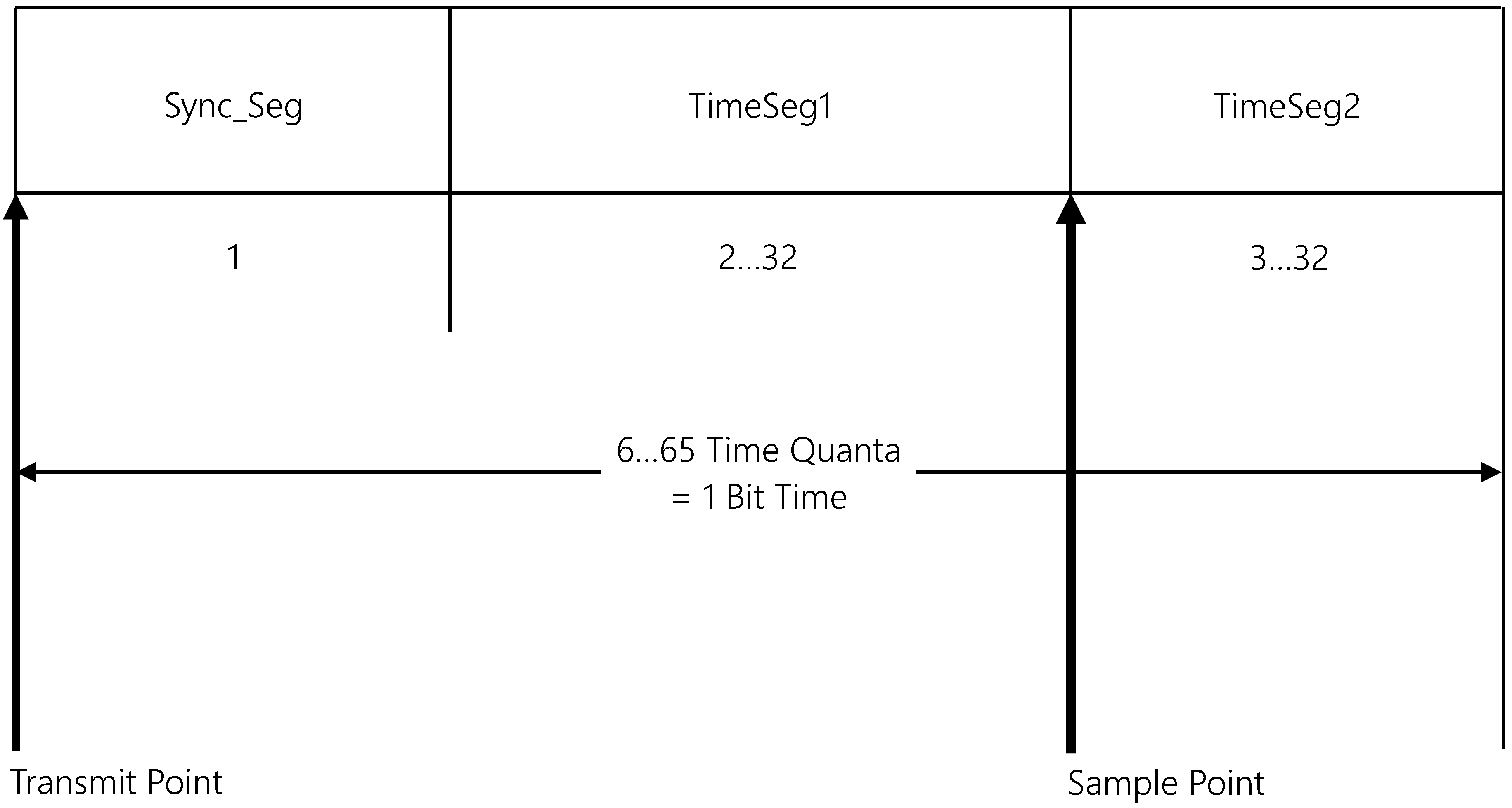
Valid ranges are 2 to 4096. The CAN peripheral is driven by a 50 MHz clock. The prescale scales this clock down to the desired time segment. For example: a 4 in this parameter will use a 12.5 MHz (80 ns period) clock as the fundamental bus time segment (TimeQuanta). |
TimeSeg1 (Optional) |
The number of TimeQuanta before the sample point. |
TimeSeg2 (Optional) |
The number of TimeQuanta after sample point. |
SJW (Optional) |
(Synchronization Jump Width) – The maximum number of TimeQuanta that a bit time can be changed by one resynchronization. Valid values are 1-4. |
CANFDPortOpen() has the following parameters:
CANPort
|
Specifies which of the 4 CAN ports to use. |
SlowBitRate
|
An integer that specifies the bit rate (Kbps) used for communications on the CAN FD port at the slower CAN FD bit rate. |
FastBitRate
|
An integer that specifies the bit rate (Kbps) used for communications on the CAN FD port at the faster CAN FD bit rate. |
Bosh/IsoMode
|
Specifies which standard to use: Bosch 1.0 CAN FD (released 2012), or ISO 11898-1 CAN FD (released 2014). |
SilentMode
|
Specifies whether messages can be received without acknowledgment. |
RestrictMode
|
Specifies whether the CAN FD port should use the Restricted Mode outlined in Section 3.3.2 of the CAN FD specification. In this mode, a CAN FD node is able to transmit and receive DATA FRAMES and REMOTE FRAMES and it gives ACKNOWLEDGE to valid frames, but it does not send ACTIVE ERROR FRAMES or OVERLOAD FRAMES. In case of an error condition or overload condition, it does not send dominant bits, instead it waits for the occurrence of BUS IDLE condition to resynchronize itself to the CAN communications. |
Termination
|
Specifies if the CAN-H and CAN-L signal are terminated with a 120 Ohm resistor. |
(Optional)
|
These parameters only apply when SlowBitRate or FastBitRate is 0. |
SlowPrescale
|
Valid ranges are 2 to 513 in ISO mode and 2 to 4097 in Bosch mode. The CAN peripheral is driven by a 160 MHz clock. The prescale scales this clock down to the desired time segment. For example: a 4 in this parameter will use a 40 MHz (25 ns period) clock as the fundamental bus time segment (TimeQuanta). |
SlowTimeSeg1
|
The number of TimeQuanta before the sample point. Valid ranges are 1 to 256 in ISO mode, and 1 to 64 in Bosch Mode. |
SlowTimeSeg2
|
The number of TimeQuanta after sample point. Valid ranges are 2 to 257 in ISO mode, and 2 to 65 in Bosch Mode. |
SlowSJW
|
(Synchronization Jump Width) – The maximum number of TimeQuanta that a bit time can be changed by one resynchronization. Valid values are 1 to 120 in ISO mode and 1 to 16 in Bosch Mode.. |
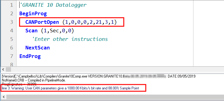
For convenience, several bitrates have been predefined. The predefined bitrates have a sample point of 85-88% in accordance with the CAN-in-Automation user group recommendations. The predefined baud rates use an SJW setting of 1. If a custom sample point, baud rate, or SJW is needed, set the baud rate parameter to 0 and use the optional parameters (Prescale, TimeSeg1, TimeSeg2, and SJW) to define the bitrate. When developing a user-specified baud rate, the following formulas are used:
Total Quanta = (1.0 + timea + timeb)
samplepoint = (100 * (timea + 1.0)) / Total Quanta
baud = (50,000,000 / (Total Quanta * Prescale))
The CRBasic pre-compiler will do these and report the baud rate and sample point found from the entered parameters.
CANRead() / CANFDRead()
CANRead() and CANFDRead() are used to read a message on a CAN port and write it to a CRBasic variable. CANPortOpen() must be declared before CANRead() or CANFDRead()is allowed. CANRead() / CANFDRead() can be used to read a signal as defined in a DBC file. It can also be used in conjunction with CANWrite() for other CAN protocols. CANRead() and CANFDRead() have the same parameters.
Syntax:
CANRead ( Dest, Reps, RunOption, RunOptTimeOut, CANPort, CanID, EXTID, MessageSize, StartBit, ReadSize, ByteOrder, ValType, MULT,Offset)
CANFDRead ( Dest, Reps, RunOption, RunOptTimeOut, CANPort, CanID, EXTID, MessageSize, StartBit, ReadSize, ByteOrder, ValType, MULT,Offset)
CANFilterRead() / CANFDFilterRead()
CANFilterRead() and CANFDFilterRead() are used to filter messages based on ID and when the filter is met, read a message on a CAN port and write it to a CRBasic variable. CANPortOpen() must be declared before CANFilterRead() / CANFDFilterRead() is allowed.
CANFilterRead() and CANFDFilterRead() have the same parameters.
Syntax:
CANFilterRead ( Dest, Reps, RunOption, RunOptTimeOut, CANPort, CanID, CANIDMask, CANIDFilter, EXTID, MessageSize, StartBit, ReadSize, ByteOrder, ValType, MULT,Offset)
CANFDFilterRead ( Dest, Reps, RunOption, RunOptTimeOut, CANPort, CanID, CANIDMask, CANIDFilter, EXTID, MessageSize, StartBit, ReadSize, ByteOrder, ValType, MULT,Offset)
CANWrite() / CANFDWrite()
CANWrite() and CANFDWrite() are used to write a message from a CRBasic variable to be transmitted onto a CAN port. CANPortOpen() must be declared before a CANWrite() / CANFDWrite() is allowed. CANWrite() / CANFDWrite() can be used to write a signal as defined in a DBC file. CANFDWrite() has an additional BRS (bit rate switch) parameter.
Syntax:
CANWrite ( OutVar, Reps, PartialFrame, CANPort, CANID, EXTID, MessageSize, StartBit, WriteSize, ByteOrder, ValType)
CANFDWrite( OutVar, Reps, PartialFrame, CANPort, BRS, CANID, EXTID, MessageSize, StartBit, WriteSize, ByteOrder, ValType)
A few notes on CANRead() / CANFDRead(), CANFilterRead() / CANFDFilterRead() and CANWrite() / CANFDWrite(): All of the type conversion is handled by the data logger. CRBasic variables defined as FLOAT will be transmitted as integers using CANWrite() (assuming ValType is unsigned or signed integer). The GRANITE 10 automatically casts the FLOAT variable to an integer and transmits it in the CAN frame as specified. When a variable is defined as a FLOAT and then read as an integer from a CAN frame, the GRANITE 10 will cast the integer, apply the multiplier and offset specified, and store it as a FLOAT.
DBC Signal Support
Both Short Cut and the CRBasic Editor have support for DBC signals.
In Short Cut, after adding a CAN Port Configuration, add a DBC Read Signal or a DBC Write Signal. Then you will be prompted to open a DBC file.
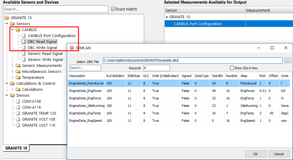
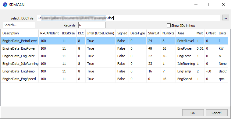
After opening a DBC file, select the signals in that DBC file. Click OK.
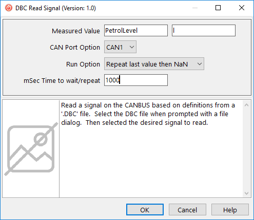
Click OK again and the program will be set up to read that signal into the variable specified. DBC Write Signal is similar.
To access the same information from CRBasic, click Select .DBC Values in the CANWrite() and CANRead() parameter entry box.
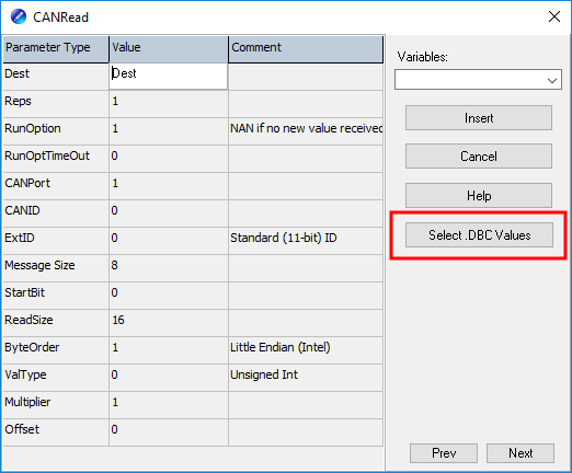
Click OK to automatically enter the required parameters.
J1979 Legislated PIDS Example
See https://www.campbellsci.com/downloads/granite10-example-can-j1979 ![]() for an example program to query an ECU (electronic control unit) for the legislated PID (Parameter ID) values once a second.
for an example program to query an ECU (electronic control unit) for the legislated PID (Parameter ID) values once a second. CANPortOpen() configures CAN 1 for this example. CANWrite() is used to request each PID, and CANRead() is used to interrupt the response and store the requested values in CRBasic Variables. This example program can be modified to read other manufacturer specific PIDs.