Current-loop measurements
CurrentSE() instruction.
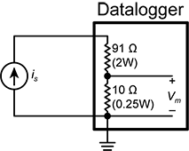
Example current-loop measurement connections
The following table shows example schematics for connecting typical current sensors and devices. See also Current-loop measurement specifications.
| Sensor type | Connection example |
|---|---|
| 2-wire transmitter using data logger power | 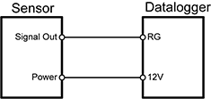
|
| 2-wire transmitter using external power | 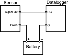
|
| 3-wire transmitter using data logger power | 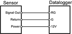
|
| 3-wire transmitter using external power | 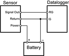
|
| 4-wire transmitter using data logger power | 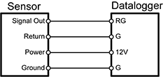
|
| 4-wire transmitter using external power | 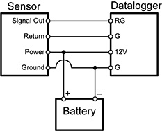
|