Ground loops
A ground loop is a condition in an electrical system that contains multiple conductive paths for the flow of electrical current between two nodes. Multiple paths are usually associated with the ground or 0 V-potential point of the circuit. Ground loops can result in signal noise, communications errors, or a damaging flow of ground current on long cables. Most often, ground loops do not have drastic negative effects and may be unavoidable. Special cases exist where additional grounding helps shield noise from sensitive signals; however, in these cases, multiple ground conductors are usually run tightly in parallel without conductive shielding material placed between the parallel grounds. If possible, ground loops should be avoided. When problems arise in a system, ground loops may be the source of the problems.
See also Grounds
Common causes
Some of the common causes of ground loops include the following:
-
The drain wire of a shielded cable is connected to the local ground at both ends, and the ground is already being carried by a conductor inside the cable. In this case, two wires, one on either side of the cable shield, are connected to the ground nodes at both ends of the cable.
-
A long cable connects the grounds of two electrical devices, and the mounting structure or grounding rod also directly connects the grounds of each device to the local earth ground. The two paths, in this case, are the connecting cable and earth itself.
-
When electrical devices are connected to a common metal chassis such as an instrument tower, the structure can create a ground path in parallel to the ground wires in sensor cables running over the structure.
-
Conductors connected to ground are found in most cables that connect to a data logger. These include sensors cables, communications cables, and power cables. Any time one of these cables connects to the same two endpoints as another cable, a ground loop is formed.
Detrimental effects
The harm from a ground loop can be seen in different ways. One consideration is the electromagnetically induced effect. This will manifest as AC noise or an AC pulse. As seen in Stray AC magnetic fields picked up in loop antenna the parallel conductive paths form an electrical loop that acts as an antenna to pick up electromagnetic energy.
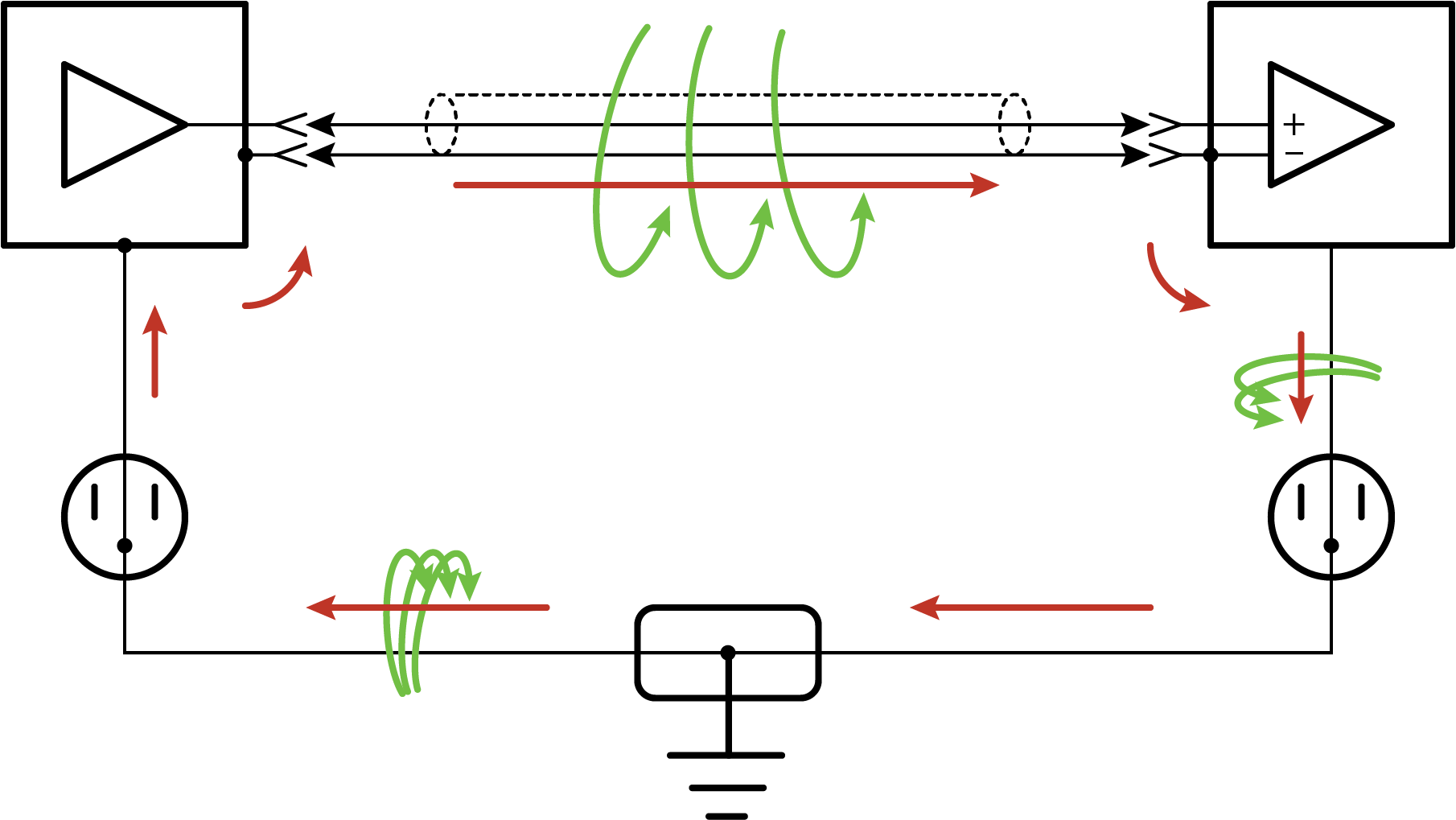
-
Relatively small electromagnetic energy: This could come from AC current on a nearby power cable, or RF energy transmitting through the air, and can cause electrical noise that
-
Larger electromagnetic energy: The antenna loop scenario can have a more damaging effect when a large current is discharged nearby. The creation of an electromagnetic pulse can induce a surge that damages attached electronic devices.
Another way ground loops affect a system is by allowing ground current to flow between devices. This can be either a DC or AC effect. For various reasons, the voltage potential between two different points on the surface of the earth is not always 0 V. Therefore, when two electrical devices are both connected to a local earth ground, there may exist a voltage difference between the two devices. When a cable is connected between the two devices at different voltages, physics dictates than an electrical current must flow between the two points through the cable. See Leakage current (AC or DC) from nearby load.
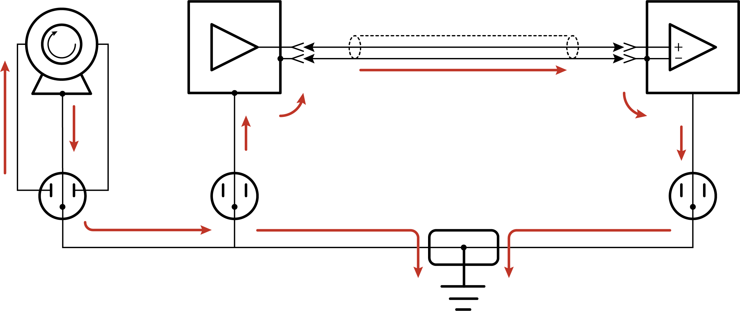
-
One effect of this DC ground current-flow is a voltage offset error in analog measurements. Errors of this sort are usually not obvious but can have meaningful effects on measurements.
-
For digital communications, an offset in the ground voltage reduces the dynamic range of the digital signals. This makes them more susceptible to noise corruption. If the ground voltage changes by one volt or more, the digital communications could stop working because the signals no longer reach the thresholds for determining the state of each bit.
-
If the ground voltage differences reach several volts, damaging effects may occur at the terminals of the electronics devices. Damage occurs when the maximum allowable voltage on the internal components is exceeded.
Severing a ground loop
To avoid or eliminate ground loops, when they are detected, requires severing the loop. Suggestions for severing ground loops include:
-
Connect the shield wire of a signal cable to ground only at one end of the cable. Leave the other end floating (not connected to ground).
-
Never intentionally use the shield (or drain wire) of a cable as a signal ground or power ground.
-
Use the mechanical support structure only as a connection for the safety ground (usually the ground lug). Do not intentionally return power ground through the structure.
-
Do not use shielded Cat5e cables for Ethernet, CPI or EPI communications.
-
For long distance communications protocols such as RS-485, RS-422, and CAN, use a Resistive Ground (RG) terminal for the ground connection. The RG terminal has a 100-ohm resistor in series with ground to limit the amount of DC current that can flow between the two endpoints while keeping the common-mode voltage in range of the transceivers. The transceivers themselves have enhanced voltage range inputs allowing for ground voltage differences of up to 7 V between endpoints.
-
For exceptional cases, use optical or galvanic isolation devices to provide a signal connection without any accompanying ground connection. These should be used only when ground loops are causing system problems and the other methods of breaking a ground loop don’t apply. These devices add expense and tend to consume large amounts of power.
