Minimizing settling errors
Settling time allows an analog voltage signal to rise or fall closer to its true magnitude prior to measurement. Default settling times, those resulting when the SettlingTime parameter is set to 0, provide sufficient settling in most cases. Additional settling time is often programmed when measuring high-resistance (high-impedance) sensors, or when sensors connect to the input terminals by long cables. The time to complete a measurement increases with increasing settling time. For example, a 1 ms increase in settling time for a bridge instruction with input reversal and excitation reversal results in a 4 ms increase in time to perform the instruction.
When sensors require long cable lengths, use the following general practices to minimize settling errors:
-
Do not use leads with PVC-insulated conductors. PVC has a high dielectric constant, which extends input settling time.
-
Where possible, run excitation leads and signal leads in separate shields to minimize transients.
-
When measurement speed is not a prime consideration, additional time can be used to ensure ample settling time.
-
In difficult cases where measurement speed is a consideration, an appropriate settling time can be determined through testing.
Measuring settling time
Settling time for a particular sensor and cable can be measured with the CR6. Programming a series of measurements with increasing settling times will yield data that indicate at what settling time a further increase results in negligible change in the measured voltage. The programmed settling time at this point indicates the settling time needed for the sensor / cable combination.
The following CRBasic Example: Measuring Settling Time presents ![]() CRBasic Campbell Scientific's BASIC-like programming language that supports analog and digital measurements, data processing and analysis routines, hardware control, and many communications protocols. code to help determine settling time for a pressure transducer using a high-capacitance semiconductor. The code consists of a series of full-bridge measurements (
CRBasic Campbell Scientific's BASIC-like programming language that supports analog and digital measurements, data processing and analysis routines, hardware control, and many communications protocols. code to help determine settling time for a pressure transducer using a high-capacitance semiconductor. The code consists of a series of full-bridge measurements (BrFull()) with increasing settling times. The pressure transducer is placed in steady-state conditions so changes in measured voltage are attributable to settling time rather than changes in pressure.
|
Measuring settling time |
|---|
|
|
The first six measurements are shown in the following table:
|
Example data from Measuring settling time program |
|||||||
|---|---|---|---|---|---|---|---|
| Timestamp | Record number | PT(1) Smp |
PT(2) Smp |
PT(3) Smp |
PT(4) Smp |
PT(5) Smp |
PT(6) Smp |
| 8/3/2017 23:34 | 0 | 0.03638599 | 0.03901386 | 0.04022673 | 0.04042887 | 0.04103531 | 0.04123745 |
| 8/3/2017 23:34 | 1 | 0.03658813 | 0.03921601 | 0.04002459 | 0.04042887 | 0.04103531 | 0.0414396 |
| 8/3/2017 23:34 | 2 | 0.03638599 | 0.03941815 | 0.04002459 | 0.04063102 | 0.04042887 | 0.04123745 |
| 8/3/2017 23:34 | 3 | 0.03658813 | 0.03941815 | 0.03982244 | 0.04042887 | 0.04103531 | 0.04103531 |
| 8/3/2017 23:34 | 4 | 0.03679027 | 0.03921601 | 0.04022673 | 0.04063102 | 0.04063102 | 0.04083316 |
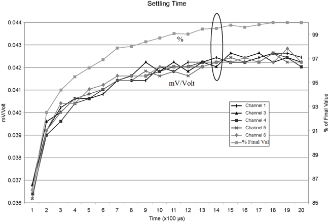
Each trace in the following image contains all twenty PT() mV/V values (left axis) for a given record number and an average value showing the measurements as percent of final reading (right axis). The reading has settled to 99.5% of the final value by the fourteenth measurement, which is contained in variable PT(14). This is suitable accuracy for the application, so a settling time of 1400 µs is determined to be adequate.