Minimizing power-related artifacts
Some ![]() VAC Volts alternating current.-to-
VAC Volts alternating current.-to-![]() VDC Volts direct current. power converters produce switching noise or
VDC Volts direct current. power converters produce switching noise or ![]() AC Alternating current (see VAC). ripple as an artifact of the ac-to-dc rectification process. Excessive switching noise on the output side of a power supply can increase measurement noise, and so increase measurement error. Noise from grid or mains power also may be transmitted through the transformer, or induced electromagnetically from nearby motors, heaters, or power lines.
AC Alternating current (see VAC). ripple as an artifact of the ac-to-dc rectification process. Excessive switching noise on the output side of a power supply can increase measurement noise, and so increase measurement error. Noise from grid or mains power also may be transmitted through the transformer, or induced electromagnetically from nearby motors, heaters, or power lines.
High-quality power regulators typically reduce noise due to power regulation. Using the 50 Hz or 60 Hz first notch frequency (fN1) option for ![]() CRBasic Campbell Scientific's BASIC-like programming language that supports analog and digital measurements, data processing and analysis routines, hardware control, and many communications protocols. analog input measurement instructions often improves rejection of noise sourced from power mains. The
CRBasic Campbell Scientific's BASIC-like programming language that supports analog and digital measurements, data processing and analysis routines, hardware control, and many communications protocols. analog input measurement instructions often improves rejection of noise sourced from power mains. The ![]() CRBasic Campbell Scientific's BASIC-like programming language that supports analog and digital measurements, data processing and analysis routines, hardware control, and many communications protocols. standard deviation output instruction,
CRBasic Campbell Scientific's BASIC-like programming language that supports analog and digital measurements, data processing and analysis routines, hardware control, and many communications protocols. standard deviation output instruction, StdDev(), can be used to evaluate measurement noise.
The data logger includes adjustable digital filtering, which serves two purposes:
-
Arrive as close as possible to the true input signal
-
Filter out measurement noise at specific frequencies, the most common being noise at 50 Hz or 60 Hz, which originate from mains-power lines.
Filtering time is inversely proportional to the frequency being filtered.
(Click image to expand/collapse display)
Minimizing electronic noise
Electronic noise can cause significant error in a voltage measurement, especially when measuring voltages less than 200 mV. So long as input limitations are observed, the ![]() PGA Programmable Gain Amplifier ignores voltages, including noise, that are common to each side of a differential-input pair. This is the common-mode voltage. Ignoring (rejecting or canceling) the common-mode voltage is an essential feature of the differential input configuration that improves voltage measurements.
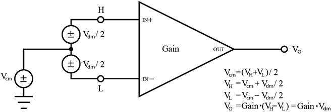
The following image illustrates the common-mode component (Vcm) and the differential-mode component (Vdm) of a voltage signal. Vcm is the average of the voltages on the V+ and V– inputs. So, Vcm = (V+ + V–)/2 or the voltage remaining on the inputs when Vdm = 0. The total voltage on the V+ and V– inputs is given as VH = Vcm + Vdm/2, and VL = Vcm – Vdm/2, respectively.
PGA Programmable Gain Amplifier ignores voltages, including noise, that are common to each side of a differential-input pair. This is the common-mode voltage. Ignoring (rejecting or canceling) the common-mode voltage is an essential feature of the differential input configuration that improves voltage measurements.
The following image illustrates the common-mode component (Vcm) and the differential-mode component (Vdm) of a voltage signal. Vcm is the average of the voltages on the V+ and V– inputs. So, Vcm = (V+ + V–)/2 or the voltage remaining on the inputs when Vdm = 0. The total voltage on the V+ and V– inputs is given as VH = Vcm + Vdm/2, and VL = Vcm – Vdm/2, respectively.