Programmable logic control
The data logger can control instruments and devices such as:
-
Controlling cellular modem or GPS receiver to conserve power.
-
Triggering a water sampler to collect a sample.
-
Triggering a camera to take a picture.
-
Activating an audio or visual alarm.
-
Moving a head gate to regulate water flows in a canal system.
-
Controlling pH dosing and aeration for water quality purposes.
-
Controlling a gas analyzer to stop operation when temperature is too low.
-
Controlling irrigation scheduling.
Control decisions can be based on time, an event, or a measured condition. Controlled devices can be physically connected to C,![]() Short Cut A CRBasic programming wizard suitable for many data logger applications. Knowledge of CRBasic is not required to use Short Cut. has provisions for simple on/off control. Control modules and relay drivers are available to expand and augment data logger control capacity.
Short Cut A CRBasic programming wizard suitable for many data logger applications. Knowledge of CRBasic is not required to use Short Cut. has provisions for simple on/off control. Control modules and relay drivers are available to expand and augment data logger control capacity.
-
C
PortSet()orWriteIO()instructions. See the CRBasic Editor help for detailed instruction information and program examples:
PortPairConfig()instruction. -
SW12 terminals can be set low (0 V) or high (12 V) using the
SW12()instruction (see the CRBasic help for more information).
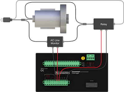
The following image illustrates a simple application wherein a C
In the case of a cell modem, control is based on time. The modem requires 12 VDC power, so connect its power wire to a data logger SW12 terminal. The following code snip turns the modem on for the first ten minutes of every hour using the TimeIsBetween() instruction embedded in an If/Then logic statement:
|
|