Wi-Fi communications option
The CR350
It also can be configured to join an existing Wi-Fi network.
A 12 VDC power source is necessary to power Wi-Fi functions of the CR350
The user is responsible for emissions if changing the antenna type or increasing the gain.
See also Communications specifications.
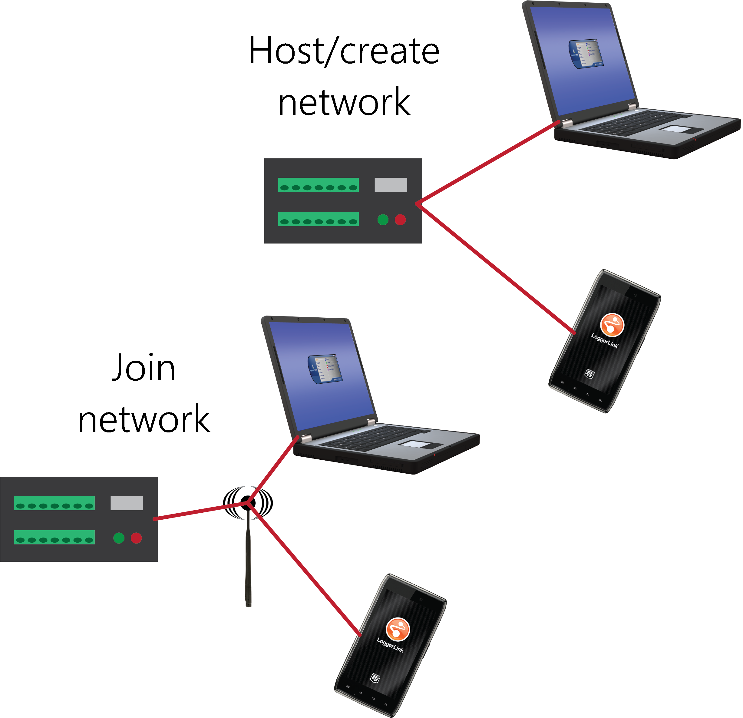
Hosting a Wi-Fi network
By default, the CR350![]() data logger support software LoggerNet, RTDAQ, and PC400 - these Campbell Scientific software applications include at least the following functions: data logger communications, downloading programs, clock setting, and retrieval of measurement data. or the LoggerLink
data logger support software LoggerNet, RTDAQ, and PC400 - these Campbell Scientific software applications include at least the following functions: data logger communications, downloading programs, clock setting, and retrieval of measurement data. or the LoggerLink ![]() mobile app for iOS and Android to connect to the CR350
mobile app for iOS and Android to connect to the CR350
See also: CR350 QuickStart Part 5 - Wi-Fi Communications  .
.
Configure the data logger to host a Wi‑Fi network
Follow these instructions to check the data logger settings or reconfigure it.
-
Ensure your CR350
-
Using
 Device Configuration Utility Software tool used to set up data loggers and peripherals, and to configure PakBus settings before those devices are deployed in the field and/or added to networks. Also called DevConfig., connect to the data logger.
 -
On the Deployment tab, click the Wi-Fi sub-tab.
-
In the Configuration list, select the Create a Network
-
Optionally, set security on the network to prevent unauthorized access by typing a password in the Password box (recommended).
-
Click Apply.
Connect your phone to the data logger over Wi-Fi
-
Press the CR350
-
Open your phone settings
 and connect to the Wi-Fi network hosted by the data logger. The default name is CR350 followed by the serial number of the data logger.
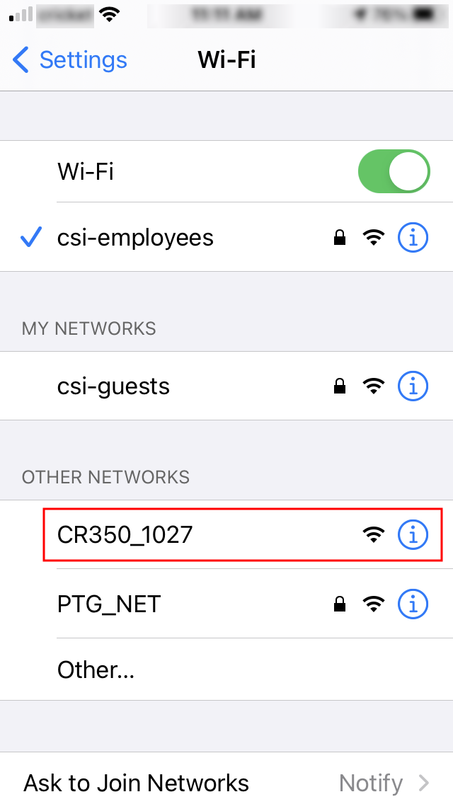
-
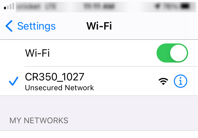
If you set a password, enter it. The resulting setting will look similar to this image.
-
Close the phone settings.
Set up LoggerLink
-
Open the
LoggerLink Mobile applications that allow a mobile device to communicate with IP, wi-fi, or Bluetooth enabled data loggers.  phone app.
 -
Read through the Getting Started information if this is your first time using LoggerLink.
-
Click + then the UDP discovery button
 .
. -
Select the CR350.

-
Save.
-
All LoggerLink features are now available until the Wi-Fi connection times out with inactivity or theCR350
Connect your computer to the data logger over Wi-Fi
-
Press the CR350
-
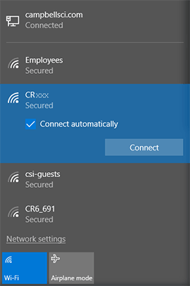
Open the Wi-Fi network settings on your computer.
-
Select the Wi-Fi-network hosted by the data logger. The default name is CR350 followed by the serial number of the data logger. In the previous image, the Wi-Fi network is CRxxx.
-
If you set a password, select the Connect Using a Security Key option (instead of a PIN) and type the password you chose.
-
Connect to this network.
Set up LoggerNet or PC400W
-
Using
data logger support software LoggerNet, RTDAQ, and PC400 - these Campbell Scientific software applications include at least the following functions: data logger communications, downloading programs, clock setting, and retrieval of measurement data., launch the EZSetup Wizard.NOTE:New software installations automatically open the EZSetup Wizard the first time they run.
-
LoggerNet Campbell Scientific's data logger support software for programming, communications, and data retrieval between data loggers and a computer. users, click Setup
 , select the View menu and ensure you are in the EZ (Simplified) view, then click Add Datalogger
 .
.
-
-
Select the IP Port connection type and click Next.
-
In the Internet IP Address field, type
192.168.67.1. This is the default data logger IP address created when the CR350 -
Click Next.
-
The
PakBus ™ A proprietary communications protocol developed by Campbell Scientific to facilitate communications between Campbell Scientific devices. Similar in concept to IP (Internet Protocol), PakBus is a packet-switched network protocol with routing capabilities. A registered trademark of Campbell Scientific, Inc. address must match the hardware settings for your data logger. The default PakBus address is 1.-
Set an Extra Response Time if you want the data logger support software to wait a certain amount of time before returning a communication failure error. This can usually be left at 00 seconds.
-
You can set a Max Time On-Line to limit the amount of time the data logger remains connected. When the data logger is contacted, communication with it is terminated when this time limit is exceeded. A value of 0 in this field indicates that there is no time limit for maintaining a connection to the data logger.
-
-
Click Next.
-
By default, the data logger does not use a security code. Therefore, the Security Code can be left at 0. If the code has been changed in the data logger, enter the new code.
Beginning with operating system
-
Click Next.
-
Review the Setup Summary. If you need to make changes, click Previous to return to a previous window and change the settings.
-
Setup is now complete. The EZSetup Wizard allows you to Finish, or you may click Next to test communications, set the data logger clock, and send a program to the data logger.
Joining a Wi-Fi network
By default, the CR350
Configure the data logger to join a Wi-Fi network
-
Ensure your CR350
-
Using
Device Configuration Utility Software tool used to set up data loggers and peripherals, and to configure PakBus settings before those devices are deployed in the field and/or added to networks. Also called DevConfig., connect to the data logger. -
On the Deployment tab, click the Wi-Fi sub-tab.
-
In the Configuration list, select the Join a Network option.
-
Next to the Network Name (SSID) box, click Browse
 to search for and select a Wi-Fi network. To join a hidden network, manually enter its SSID.
 -
If the network is a secured network, you must enter the password in the Password box and add any additional security in the Enterprise section of the window.
-
Enter the IP Address, Network Mask, and Gateway. These values should be provided by your network administrator. A static IP address is recommended.
-
Alternatively, you can use an IP address assigned to the data logger via DHCP. To do this, make sure the IP Address is set to
0.0.0.0. Click Apply to save the configuration changes. Then reconnect. The IP information obtained through DHCP is updated and displayed in the Status section of the Wi-Fi subtab. Note, however, that this address is not static and may change. An IP address here of 169.254.###.### means the data logger was not able to obtain an address from the DHCP server. Contact your network administrator for help.
-
-
Click Apply.
Set up LoggerNet or PC400W
For each data logger you want to connect to the network, you must follow the instruction in Configure the data logger to join a Wi-Fi network.
-
Using
data logger support software LoggerNet, RTDAQ, and PC400 - these Campbell Scientific software applications include at least the following functions: data logger communications, downloading programs, clock setting, and retrieval of measurement data., launch the EZSetup Wizard.NOTE:New software installations automatically open the EZSetup Wizard the first time they run.
-
LoggerNet Campbell Scientific's data logger support software for programming, communications, and data retrieval between data loggers and a computer. users, click Setup, select the View menu and ensure you are in the EZ (Simplified) view, then click Add Datalogger.
-
-
Click Next.
-
Select
-
Select the IP Port connection type and click Next
-
Use UDP Search... to find and Add the data logger IP address.
-
Click Next.
-
The
PakBus ™ A proprietary communications protocol developed by Campbell Scientific to facilitate communications between Campbell Scientific devices. Similar in concept to IP (Internet Protocol), PakBus is a packet-switched network protocol with routing capabilities. A registered trademark of Campbell Scientific, Inc. address must match the hardware settings for your data logger. The default PakBus address is 1.-
Set an Extra Response Time if you want the data logger support software to wait a certain amount of time before returning a communication failure error. This can usually be left at 00 seconds.
-
You can set a Max Time On-Line to limit the amount of time the data logger remains connected. When the data logger is contacted, communication with it is terminated when this time limit is exceeded. A value of 0 in this field indicates that there is no time limit for maintaining a connection to the data logger.
-
-
Click Next.
-
By default, the data logger does not use a security code. Therefore, the Security Code can be left at 0. If the code has been changed in the data logger, enter the new code.
Beginning with operating system
-
Click Next.
-
Review the Setup Summary. If you need to make changes, click Previous to return to a previous window and change the settings.
-
Setup is now complete. The EZSetup Wizard allows you to Finish, or you may click Next to test communications, set the data logger clock, and send a program to the data logger.
Wi-Fi configurations and mode button
Configure the Wi-Fi mode and button using Device Configuration Utility software.
Join a Network
The CR350 will scan for available Wi-Fi networks and attempt to join the network specified by the SSID field. If the data logger cannot join the desired SSID (for example, the network is out of range or there are incorrect parameters), it will go to a low power state and retry about every one minute.
When this mode is selected, the Wi-Fi button is disabled. The WIFI LED
Create a Network
The data logger will create and host a Wi-Fi network. Enter the desired name of the network in the SSID field. A network created by the CR350 supports up to eight joinees. If a password is supplied, the network created will be secured by WPA2 encryption. If no password is supplied, the network created will be an open network with no encryption.
When this mode is selected, the Wi-Fi button is disabled. The WIFI LED
Normally Off, Join Network on Button Press (default)
The Wi-Fi will be normally turned off until the Wi-Fi button is pressed. When the button is pressed, the CR350 will attempt to join the network specified. The Wi-Fi will stay powered, and joined to the network until it times out or until the button is pressed again. Then the Wi-Fi shuts off. The timeout will be a minimum of five minutes with a two minute refresh on any communications sent by the data logger.
When the button is pressed, the WIFI LED
Normally Off, Create Network on Button Press
The Wi-Fi will be normally turned off until the Wi-Fi button is pressed. When the button is pressed, the data logger will create and host the network specified. The Wi-Fi will stay powered and hosting the network until it times out or until the button is pressed again. Then the Wi-Fi shuts off. The timeout will be a minimum of five minutes with a two minute refresh on any communications sent by the data logger.
When the button is pressed, the WIFI LED
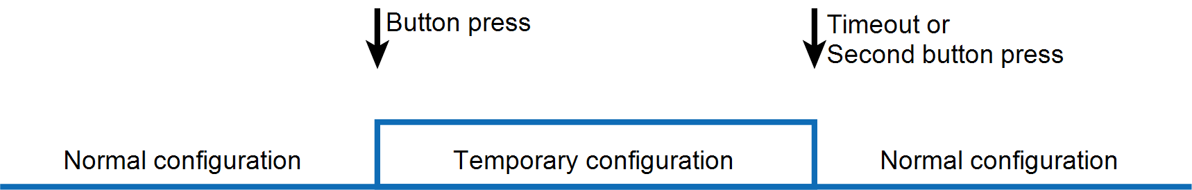
Join Network, Create Network on Button Press
The CR350 will attempt to join the network specified. It will remain joined to the network until the Wi-Fi button is pressed. When the button is pressed, the data logger will disassociate with the previously joined network and create and host an open (unencrypted) network with the name model_serialnumber. The data logger will continue hosting the network until it times out or until the button is pressed again. Then the Wi-Fi will switch back to join mode and attempt to join the network specified. The timeout on the hosted network will be a minimum of five minutes with a two minute refresh on any communication sent to the data logger .
During the time the data logger is creating and hosting the temporary network, no communications can take place on the previously joined network until the created network has timed out and the data logger re-joins the other network.
The WIFI LED
Disable
Wi-Fi communications will be disabled and the module turned off.
When the Wi-Fi configuration is set to Join a Network or Create a Network the Wi-Fi button is disabled.
Wi-Fi LED indicator
When the data logger is powered, the Wi-Fi LED
-
Off: Insufficient power, Wi-Fi disabled, or data logger failed to join or create a network (periodic retries will occur).
-
Solid for 2 seconds: Attempting to join or create a network.
-
Flashing: Successfully joined or created a network. Flashes with network activity and once every four seconds when there is no activity.