Current-loop measurements
CurrentSE() instruction.
Use a CURS100 terminal input module when an application needs more than 2 current inputs or measurements. For detailed instructions, see http://www.campbellsci.com/curs100 ![]() .
.
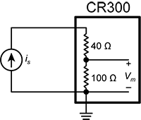
Voltage ranges for current measurements
The data logger measures the current through the use of a 100 Ω resistor. Thus, like a single-ended voltage instruction, it requires a voltage range option. In general, use the smallest fixed-input range that accommodates the full-scale output of the transmitter. This results in the best measurement ![]() accuracy The degree to which the result of a measurement, calculation, or specification conforms to the correct value or a standard. and
accuracy The degree to which the result of a measurement, calculation, or specification conforms to the correct value or a standard. and ![]() resolution The smallest interval measurable..
resolution The smallest interval measurable..
To select the appropriate voltage range, the expected current output range must be known. Using Ohm’s Law, multiply the maximum expected current by 100 Ω to find the maximum voltage to be measured. Because the maximum voltage input is 2500 mV, the maximum current input must be 25 mA or less.
Example current-loop measurement connections
The following table shows example schematics for connecting typical current sensors and devices. See also Current-loop measurement specifications.
| Sensor type | Connection example |
|---|---|
| 2-wire transmitter using data logger power | 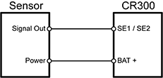
|
| 2-wire transmitter using external power | 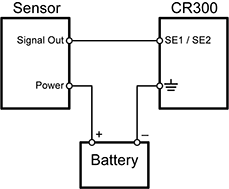
|
| 3-wire transmitter using data logger power | 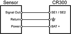
|
| 3-wire transmitter using external power | 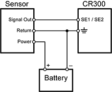
|
| 4-wire transmitter using data logger power | 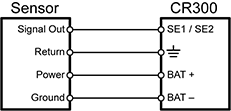
|
| 4-wire transmitter using external power | 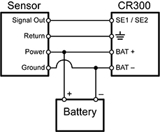
|