Current-loop measurements
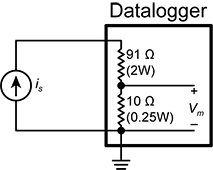
RG terminals can be configured to make analog current measurements using the CurrentSE() instruction. When configured to measure current, terminals each have an internal resistance of 101 Ω in the current measurement loop. The return path of the sensor must be connected directly to the RG terminal. The following image shows a simplified schematic of a current measurement.
Example current-loop measurement connections
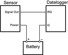
The following table shows example schematics for connecting typical current sensors and devices. See also Current-loop measurement specifications.
| Sensor type |
Connection example |
| 2-wire transmitter using data logger power |
|
| 2-wire transmitter using external power |
|
| 3-wire transmitter using data logger power |
|
| 3-wire transmitter using external power |
|
| 4-wire transmitter using data logger power |
|
| 4-wire transmitter using external power |
|


