Wiring panel and terminal functions
The CR1000X/CR1000Xe wiring panel provides ports and removable ![]() terminals Point at which a wire (or wires) connects to a wiring panel or connector. Wires are usually secured in terminals by screw- or lever-and-spring actuated gates with small screw- or spring-loaded clamps. for connecting sensors, power, and communications devices. It is protected against surge, over-voltage, over-current, and reverse power. The wiring panel is the interface to most data logger functions so studying it is a good way to get acquainted with the data logger. Functions of the terminals are broken down into the following categories:
terminals Point at which a wire (or wires) connects to a wiring panel or connector. Wires are usually secured in terminals by screw- or lever-and-spring actuated gates with small screw- or spring-loaded clamps. for connecting sensors, power, and communications devices. It is protected against surge, over-voltage, over-current, and reverse power. The wiring panel is the interface to most data logger functions so studying it is a good way to get acquainted with the data logger. Functions of the terminals are broken down into the following categories:
- Analog input
- Pulse counting
- Analog output
- Communications
- Digital I/O
- Power input
- Power output
- Power ground
- Signal ground
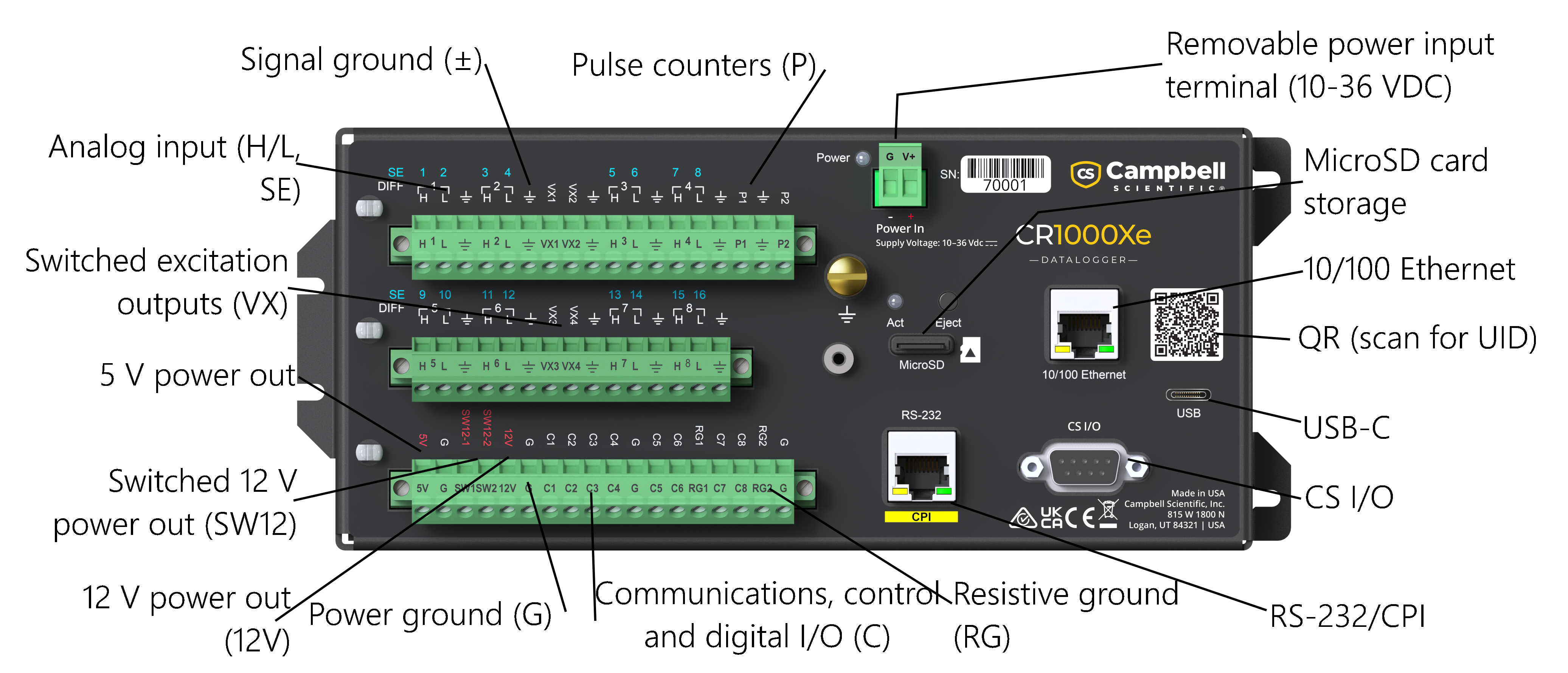
CR1000Xe wiring panel
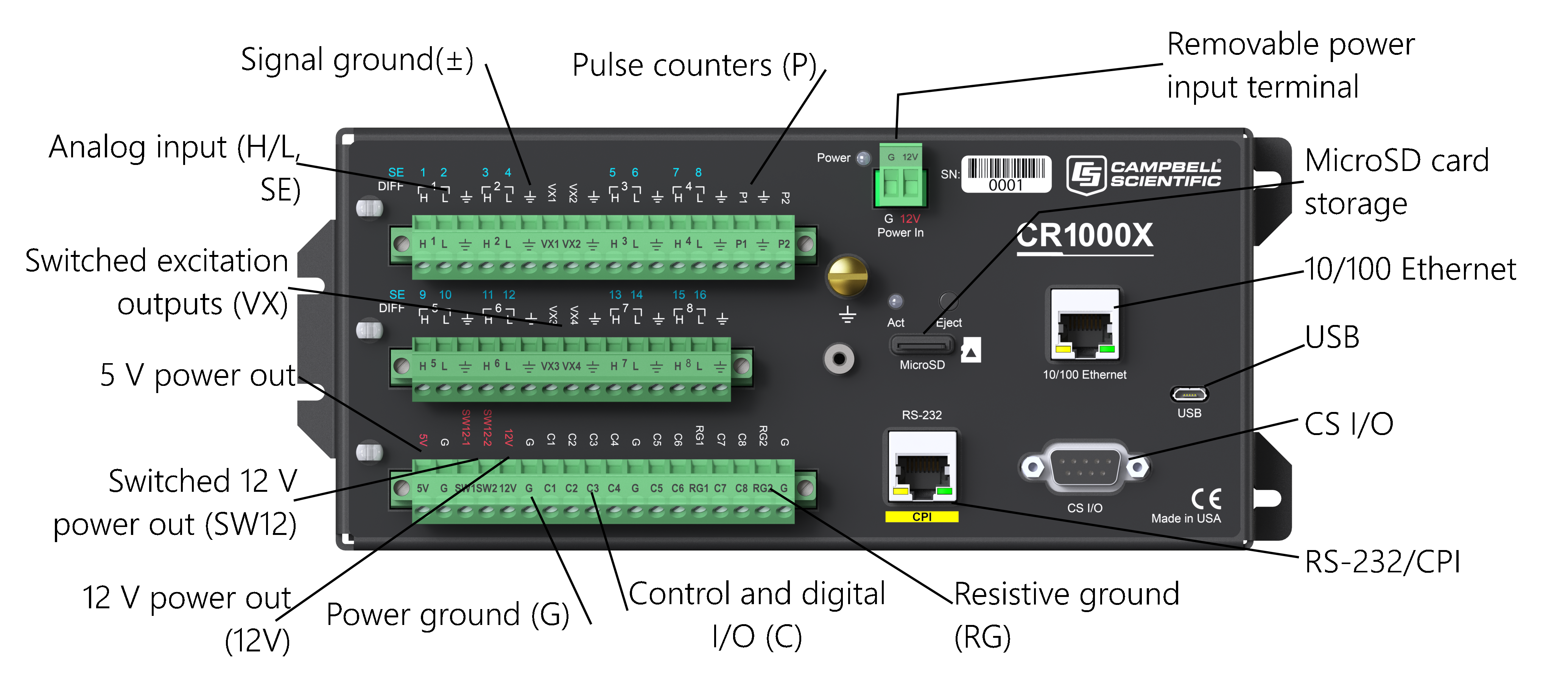
CR1000X Wiring panel
|
Analog input terminal functions |
||||||||||||||||||
|---|---|---|---|---|---|---|---|---|---|---|---|---|---|---|---|---|---|---|
| SE DIFF |
1 2 ┌1┐ H L |
3 4 ┌2┐ H L |
5 6 ┌3┐ H L |
7 8 ┌4┐ H L |
9 10 ┌5┐ H L |
11 12 ┌6┐ H L |
13 14 ┌7┐ H L |
15 16 ┌8┐ H L |
RG1 | RG2 | ||||||||
| Single-Ended Voltage | ✓ | ✓ | ✓ | ✓ | ✓ | ✓ | ✓ | ✓ | ✓ | ✓ | ✓ | ✓ | ✓ | ✓ | ✓ | ✓ | ||
| Differential Voltage | H | L | H | L | H | L | H | L | H | L | H | L | H | L | H | L | ||
| Ratiometric/Bridge | ✓ | ✓ | ✓ | ✓ | ✓ | ✓ | ✓ | ✓ | ✓ | ✓ | ✓ | ✓ | ✓ | ✓ | ✓ | ✓ | ||
| Thermocouple | ✓ | ✓ | ✓ | ✓ | ✓ | ✓ | ✓ | ✓ | ✓ | ✓ | ✓ | ✓ | ✓ | ✓ | ✓ | ✓ | ||
| Current Loop | ✓ | ✓ | ||||||||||||||||
| Period Average |
✓ | ✓ | ✓ | ✓ | ✓ | ✓ | ✓ | ✓ | ✓ | ✓ | ✓ | ✓ | ✓ | ✓ | ✓ | ✓ | ||
|
Pulse counting terminal functions |
|||
|---|---|---|---|
| P1 | P2 | C1-C8 | |
| Switch-Closure | ✓ | ✓ | ✓ |
| High Frequency | ✓ | ✓ | ✓ |
| Low-level AC | ✓ | ✓ | |
Conflicts can occur when a control port pair is used for different instructions (TimerInput(), PulseCount(), SDI12Recorder(), WaitDigTrig()). For example, if C1 is used for SDI12Recorder(), C2 cannot be used for TimerInput(), PulseCount(), or WaitDigTrig().
|
Analog output terminal functions |
|
|---|---|
| VX1-VX4 | |
| Switched Voltage Excitation | ✓ |
|
Voltage Output |
|||||||
|---|---|---|---|---|---|---|---|
| C1-C81 | VX1-VX4 | 5V | 12V | SW12-1 | SW12-2 | SW12-CSIO | |
| 5 VDC | ✓ | ✓ | ✓ | ||||
| 3.3 VDC | ✓ | ✓ | |||||
| 12 VDC | ✓ | ✓ | ✓ |
✓ (CR1000Xe only) |
|||
| C1 | C2 | C3 | C4 | C5 | C6 | C7 | C8 | RS-232/CPI | |
|---|---|---|---|---|---|---|---|---|---|
| SDI-12 | ✓ | ✓ | ✓ | ✓ | |||||
| GPS | PPS | Rx | Tx | Rx | Tx | Rx | Tx | Rx | |
| TTL 0-5 V1 | Tx | Rx | Tx | Rx | Tx | Rx | Tx | Rx | |
| LVTTL 0-3.3 V1 | Tx | Rx | Tx | Rx | Tx | Rx | Tx | Rx | |
| RS-232* |
|
|
|
|
Tx | Rx | Tx | Rx | ✓ |
| (CR1000Xe only) | |||||||||
| RS-485 (Half Duplex) |
|
|
|
|
A- | B+ | A- | B+ | |
| (CR1000Xe only) | |||||||||
| RS-4852 (Full Duplex) |
|
|
|
|
Tx- | Tx+ | Rx- | Rx+ | |
| (CR1000Xe only) | |||||||||
| I2C | SCL | SDA | SCL | SDA | SCL | SDA | SCL | SDA | |
| SPI | SCLK | COPI | CIPO | SCLK | COPI | CIPO | |||
| SDM3 | Data | Clk | Enabl | Data | Clk | Enabl | |||
| CPI/CDM | ✓ | ||||||||
While ComC1–ComC3 are compatible with RS-232 signals on the CR1000Xe, only ComC5 and ComC7 are compatible with RS-232 signals on the CR1000X. ComC1 and ComC3 on the CR1000X are not designed to handle RS-232 signals, and long-term exposure—such as when connecting an RV50(X) modem—can damage the data logger. An advantage of the CR1000Xe is that ComC1, ComC3, ComC5, and ComC7 all support RS-232 signals, whereas the CR1000X supports RS-232 only on ComC5 and ComC7.
|
Digital I/O terminal functions |
|
|---|---|
| C1-C8 | |
| General I/O | ✓ |
| Pulse-Width Modulation Output | ✓ |
| Timer Input | ✓ |
| Interrupt | ✓ |
| Quadrature | ✓ |